
Containment vessel long-term pressure relief filtration system

A filtration system and containment technology, applied in nuclear power generation, climate sustainability, emergency protection devices, etc., can solve the problems of insufficient contact time, harsh operating conditions, slow chemical reaction rate, etc., to improve the removal efficiency and ensure Stable, good removal effect

Active Publication Date: 2017-03-15
HARBIN ENG UNIV
View PDF11 Cites 9 Cited by
  • Summary
  • Abstract
  • Description
  • Claims
  • Application Information

AI Technical Summary

Problems solved by technology

The filter has high filtration efficiency for submicron aerosol and elemental iodine, but poor filtration efficiency for gaseous methyl iodide
Due to the low solubility of methyl iodide gas and the slow chemical reaction rate with the solution, the improvement of its removal efficiency has become a common problem in the design and improvement of the containment pressure relief filtration system. How to improve the methyl iodide gas while ensuring the system is simple and reliable? The removal efficiency of iodine gas is an important problem to be solved at present
In addition, in the existing wet filtration system, since the decay heat released by radioactive substances will cause the solution to evaporate, the running time of the system generally does not exceed 24 hours. Therefore, how to prolong the running time of the system in the late stage of a severe accident is a system design that needs to be considered another important question
[0005] In the existing reactor containment filtration system, a combination of wet and dry filtration is commonly used. For example, in the patents CN204242599U and CN102723114A, it is mentioned that Venturi scrubbers and metal fiber filters are used to carry out Filtration, but the filtration efficiency of the system is not given in the two patents, especially the filtration efficiency of methyl iodide gas
In the U.S. Patent No., it is mentioned in the patent of US 8142665 B2 that the removal efficiency of the solution to methyl iodide gas is improved by adding a phase transfer catalyst methyl trioctyl ammonium chloride (Aliquat336) in the solution, but due to Aliquat336 itself has the characteristics of flammability and agglomeration, it is difficult to realize the application in engineering
In addition, it is also mentioned in the literature that filters equipped with absorbent materials such as activated carbon or silver zeolite can be used to improve the removal efficiency of methyl iodide gas. On the one hand, this method will increase the complexity of the system and increase the system cost. On the one hand, absorbent materials such as activated carbon and silver zeolite have strict requirements on the use conditions and are also prone to failure, which is still not the best way to improve the absorption efficiency of methyl iodide gas
[0006] The ability of Venturi scrubber to remove solid particles is closely related to particle diameter. When the particle diameter is greater than 0.5 μm, Venturi scrubber has excellent removal performance for solid particles. At this time, inertial collision is the main mechanism of dust particle removal; When the particle diameter is less than 0.5 μm, the influence of the Brownian motion of the particle is gradually obvious, and the dust collection efficiency of the common Venturi scrubber will deteriorate rapidly
Venturi scrubbers are also commonly used in the field of gas absorption, but the absorption efficiency of gas is selective. When the absorption rate between gas and chemical solution is fast, the degassing efficiency of Venturi scrubber is very high, while for In the case of slow absorption rate, the degassing efficiency is difficult to meet the requirements due to insufficient contact time

Method used


Image

  • Containment vessel long-term pressure relief filtration system
  • Containment vessel long-term pressure relief filtration system
  • Containment vessel long-term pressure relief filtration system

Examples


Embodiment Construction

[0017] The present invention will be further described in detail below in conjunction with the accompanying drawings and specific embodiments.

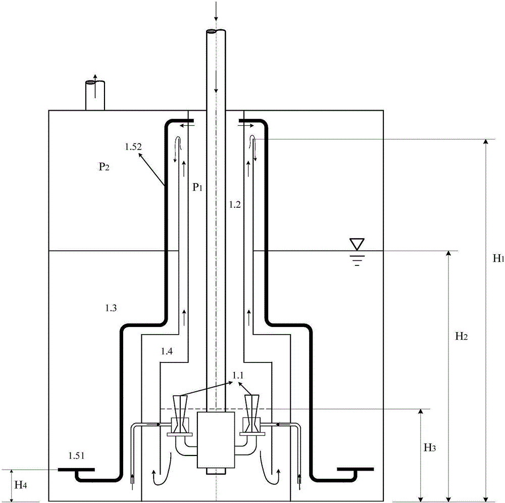
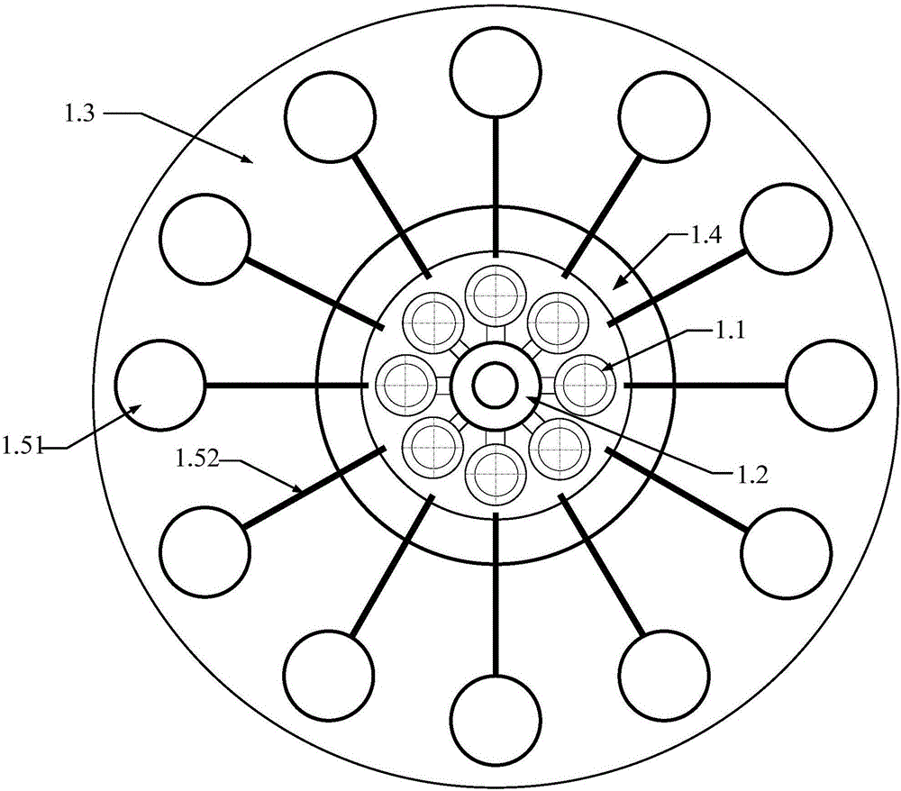
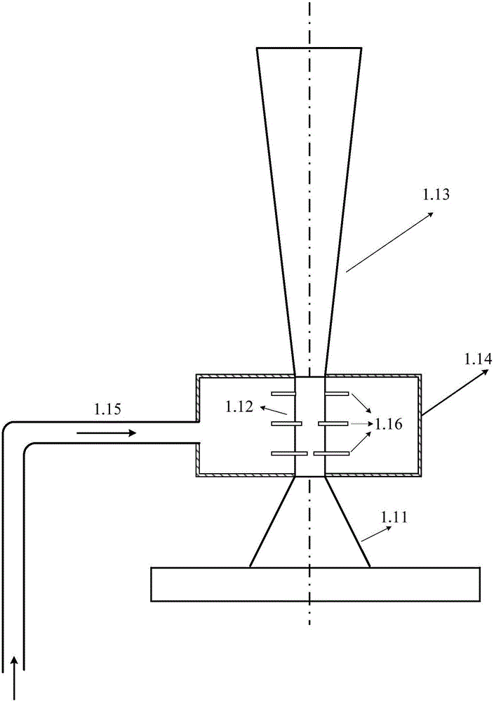
[0018] combined with Figure 1-4 , the present invention includes: (1) a self-priming Venturi scrubber 1.1 with high dust and gas removal efficiency; (2) a Venturi scrubber chamber 1.2 located in the central area of ​​the system for enveloping the Venturi scrubber, At the same time, the static pressure in the upper space of the chamber provides the driving force for the gas to enter the bubbling chamber 1.3; (3) a bubble generation system for dividing the continuous gas phase into discrete bubbles; (4) the bubbling absorption system located at the periphery of the system Chamber 1.3, the gas forms a uniform bubbly flow in the chamber, which is used to improve the absorption efficiency of methyl iodide gas and the removal efficiency of small particle size aerosols; (5) the boundary of Venturi scrubber chamber 1.2 and the bubbling chamb...


PUM


Abstract

The invention provides a containment vessel long-term pressure relief filtration system. A circular liquid flowing channel is arranged in a housing; a bubbling chamber is formed between an outer wall of the circular liquid flowing channel and an inner wall f the housing; an inversed T-shaped cylindrical venturi scrubber chamber is formed in the inner wall of the circular fluid flowing channel; the bottom of the venturi scrubber chamber communicates with the lower end of the circular fluid flowing channel; self-suction venturi scrubbers are evenly arranged in the circumference direction of the venturi scrubber chamber; the lower inlet of each self-suction venturi scrubber communicates with a gas discharging pipe of a containment vessel; the upper end of the circular fluid flowing channel communicates with the bubbling chamber; bubbling systems are evenly arranged the circumference direction of the bubbling chamber; each bubbling system includes bubbling hole plates and communication pipes; and one end of each communication pipe is connected to the corresponding bubbling hole plate, and the other end of each communication pipe communicates with the upper part of the venturi scrubber chamber. The containment vessel long-term pressure relief filtration system has a higher removing efficiency, and can especially and remarkably improve the removing efficiency of methyl iodide gas.

Description

technical field [0001] The invention relates to a containment long-term pressure relief filter system, which is mainly used for the overpressure protection of the containment and the retention of radioactive substances in the late stage of a severe accident in a nuclear power plant, and is also applicable to the process of industrial dust removal and gas removal. Background technique [0002] As a clean and efficient energy source, nuclear power is increasingly favored by people. Although the design of PWR nuclear power plants has implemented the principle of safety in depth to ensure the safety of nuclear power plants under design basis accidents, there is still a risk of accidents beyond design basis in nuclear power plants, which will lead to core meltdown pressure vessels and superimposed full-scale accidents. Serious accidents involving power outages. In the event of a severe accident beyond the design basis, the high-temperature and high-pressure coolant in the primar...

Claims


Application Information

Patent Timeline
IPC IPC(8): G21F9/02G21C9/004
CPCG21C9/004G21F9/02Y02E30/30
Inventor 周艳民谷海峰王晨温济铭孙中宁阎昌琪曹夏昕
Owner HARBIN ENG UNIV
Learn More