Machining method for numerical control turning of circular arc chamfer on shaft excircle surface

An external surface, arc chamfering technology, applied in turning equipment, turning equipment, metal processing equipment, etc., can solve the problems of sharp edges and the unsmooth connection of the external surface of the shaft, so as to reduce the processing cost and avoid processing. The effect of low precision and ensuring assembly quality

Inactive Publication Date: 2017-03-08
王爱民
View PDF0 Cites 4 Cited by
  • Summary
  • Abstract
  • Description
  • Claims
  • Application Information

AI Technical Summary

Problems solved by technology

[0005] The technical problem to be solved by the present invention is to overcome the problem that the arc chamfering of the end of the shaft in the prior art cannot be smoothly connected with the outer circular surface of the shaft, and there are sharp edges, and to provide a method that can ensure the arc chamfering. It is a machining method of circular chamfering on the outer surface of a CNC turning shaft that is smoothly connected with the outer surface of the shaft, can reduce processing procedures, reduce operating costs, and improve machining accuracy and efficiency.

Method used


Image

  • Machining method for numerical control turning of circular arc chamfer on shaft excircle surface
  • Machining method for numerical control turning of circular arc chamfer on shaft excircle surface

Examples


Embodiment 1

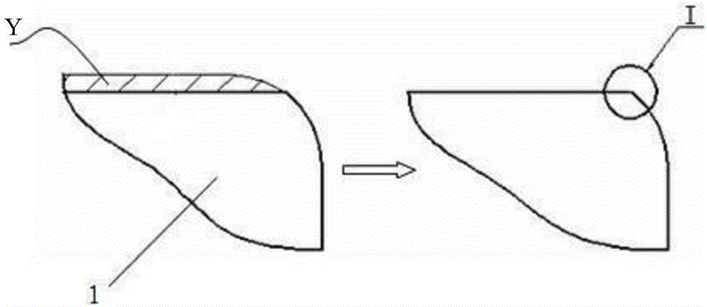
[0023] Such as figure 2 As shown, there is a circular chamfer R2 at the end of axis 1. We set the outer circular surface of the axis as Xb. When processing R2 and Xb at one time, the machining process can be programmed in advance according to the design requirements. After determining the NC turning When drawing the graph, determine the arc chamfering R2 and Xb of the shaft to be turned as a combined curve Xa2, and set the processing parameters of the turning machine tool as S=2500r / min, F=70mm / min. S is the speed, F is the feed rate, and Xa2 is processed at one time, and the outer surface of the shaft is smoothly connected with the arc chamfer.

Embodiment 2

[0025] Such as figure 2 As shown, the neck of shaft 1 has a circular chamfer R1, we set the outer surface of the shaft as Xb, and when processing R1 and Xb at one time, the machining process can be programmed in advance according to the design requirements. When drawing the graph, determine the arc chamfering R1 and Xb of the shaft to be turned as a combined curve Xa1, and set the processing parameters of the turning machine tool as S=2500r / min, F=70mm / min. S is the speed, F is the feed rate, Xa1 is processed at one time, and the outer surface of the shaft is smoothly connected with the arc chamfer.

Embodiment 3

[0027] Such as figure 2 As shown, the neck of shaft 1 has a circular chamfer R1, and the end of shaft 1 has a circular chamfer R2. We set the outer surface of the shaft as Xb. When processing R1, Xb and R2 at one time, it can be processed according to The design requires NC programming in advance for the machining process. When determining the NC turning curve, determine the arc chamfering R1, Xb and R2 of the turning axis as a combined curve Xa, and set the processing parameters of the turning machine tool as S= 2500r / min, F=70mm / min. S is the speed, F is the feed rate, and Xa is processed at one time, and the outer surface of the shaft is smoothly connected with the arc chamfer.

[0028] Preferably, in the above three embodiments, the knives used are all ceramic knives. Because ceramic knives have the advantages of better durability, higher hardness, wear resistance, better anti-sticking properties, and less wear and tear.

[0029] Positive progress effect of the present...


PUM


Abstract

The invention provides a machining method for numerical control turning of a circular arc chamfer on a shaft excircle surface. The machining method comprises the following steps of: A. carrying out numerical control programming on a machining process in advance according to design requirements, and determining a circular arc chamfer R of a shaft needing to be turned and the shaft excircle surface Xb as a combination curve Xa when a numerical control turning curve graph is determined; B. setting machining parameters of a turning machine as the rotating speed S being 2500r / min and the feeding speed F being 70mm / min; and C. machining the Xa at one time to cause the shaft excircle surface and the circular arc chamfer to be in smooth connection. The machining method has the beneficial effects that the smooth connection of the circular arc chamfer and the shaft excircle surface is ensured; a machining procedure can also be reduced; the operating cost is reduced; the machining accuracy and efficiency are improved; and the machining method has very wide application prospect.

Description

technical field [0001] The invention relates to a machining method, in particular to a machining method for circular chamfering of the outer circular surface of a numerically controlled turning shaft. Background technique [0002] When designing various shaft and disk parts, the end of shaft 1 is usually designed as a circular chamfer R, such as figure 1 As shown, in the turning process, the transition arc of the chamfering part is often directly processed according to the drawing, especially when the arc chamfering of such parts is processed by the CNC machine tool, it is completely in accordance with the design requirements in the programming process. Compile and process a complete R arc, and only leave the grinding amount of Y thickness for the grinding process of the next process. After CNC turning, the outer diameter surface of the shaft usually needs to be ground in the subsequent process. In most cases, the chamfering part is generally not subjected to grinding and f...

Claims


Application Information

Patent Timeline
Patent Type & Authority Applications(China)
IPC IPC(8): B23B5/16B23B27/00
CPCB23B5/16B23B27/00B23B2220/08
Inventor 王爱民
Owner 王爱民
Why Eureka
Try Eureka