
Ceramic energy-saving furnace kiln capable of high-efficiently replaying, recovering and cooling waste heat

An energy-saving furnace and ceramic technology, which is applied in the field of ceramic firing, can solve problems such as single layout and connection mode, affecting the molding of ceramic products, and mutual interference of pipelines, so as to improve the efficiency of ceramic enterprises, improve product qualification rate, and improve product quality. Effect

Active Publication Date: 2017-02-22
DLT TECH CO LTD
View PDF8 Cites 8 Cited by
  • Summary
  • Abstract
  • Description
  • Claims
  • Application Information

AI Technical Summary

Problems solved by technology

However, in this patent, the layout and connection method of the tail cooling heat extraction main pipe, circulating air pipe, heat exchange air pipe, and multiple indirect cooling branch pipes are single, the recovery volume is low, and the mutual interference between the pipes leads to large temperature fluctuations, which affects the molding of ceramic products.

Method used


Image

  • Ceramic energy-saving furnace kiln capable of high-efficiently replaying, recovering and cooling waste heat
  • Ceramic energy-saving furnace kiln capable of high-efficiently replaying, recovering and cooling waste heat
  • Ceramic energy-saving furnace kiln capable of high-efficiently replaying, recovering and cooling waste heat

Examples


Embodiment Construction

[0034] In order to make the object, technical solution and advantages of the present invention clearer, the present invention will be further described in detail below in conjunction with the accompanying drawings. It is only stated here that the words for directions such as up, down, left, right, front, back, inside, and outside that appear or will appear in the text of the present invention are only based on the accompanying drawings of the present invention, and are not specific to the present invention. limited.

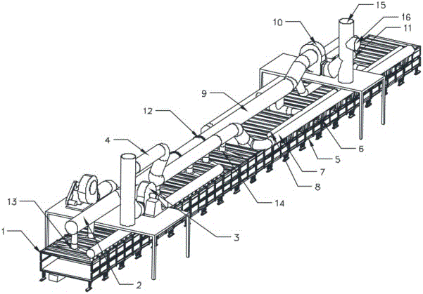
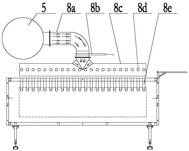
[0035] see Figure 2~Figure 7 , Figure 2~Figure 7 It shows the specific structure of the ceramic energy-saving kiln for high-efficiency relay recovery of cooling waste heat of the present invention, which sequentially includes a rapid cooling zone, a slow cooling zone and a tail cooling zone, specifically:

[0036] Tail cooling area:

[0037] The tail cooling area is provided with a tail cooling area exhaust hood 42, a tail cooling area exhaust pipe 3 and a h...


PUM


Abstract

The invention discloses a ceramic energy-saving furnace kiln capable of high-efficiently replaying, recovering and cooling waste heat. The ceramic energy-saving furnace kiln capable of high-efficiently replaying, recovering and cooling the waste heat comprises a rapid cooling zone, a slow cooling zone and a tail cooling zone. Tail cooling zone draught hoods, a tail cooling zone exhaust pipe and a heat-extraction fan are arranged on the tail cooling zone; a slow cooling zone discharge pipe, a plurality of slow cooling zone air supply pipe groups, a plurality of slow cooling zone discharge pipe groups, a slow cooling zone exhaust pipe and a heat exchange fan are arranged on the slow cooling zone; a combustion fan, an air supply main pipe and a nozzle are arranged on the rapid cooling zone; and a rapid cooling zone air supply pipe group and a rapid cooling zone discharge pipe group are arranged on the air supply main pipe. By adopting the ceramic energy-saving furnace kiln capable of high-efficiently replaying, recovering and cooling the waste heat provided by the invention, a pipeline structure for recovering hot air is formed through a high-efficiently continuous replaying manner, cooling heat generated when ceramics are cooled at each stage is fully recycled, the combustion consumption during a drying and sintering process is remarkably reduced, the pollution on the environment caused by a heat source can be effectively reduced, and the product quality can also be improved.

Description

technical field [0001] The invention relates to the technical field of ceramic firing, in particular to a ceramic energy-saving kiln for efficiently relaying and recovering cooling waste heat. Background technique [0002] In the ceramic industry, ceramic products need to be sintered at high temperature through a kiln, cooled and shaped to achieve a certain strength for people to use. Ceramic products need to absorb heat during the firing process, and the heat needs to be released during the cooling process. [0003] In order to improve the cooling efficiency, the ceramic products are generally cooled by segmental cooling according to the characteristics of the ceramic products. The cooling zone of the existing horizontal kiln (such as roller kiln, tunnel kiln) is generally subdivided into a rapid cooling zone, a slow cooling zone and a tail cooling zone. Among them, the rapid cooling zone is the first cooling stage after high-temperature firing. The cold zone is the secon...

Claims


Application Information

Patent Timeline
IPC IPC(8): F27D17/00
CPCF27D17/004Y02P10/25Y02P80/15
Inventor 彭智健何万贤梁远斌杨洋
Owner DLT TECH CO LTD
Learn More