
A pipe cleaner with automatic braking device

A technology for automatic braking and pigging, applied in the field of pigging, can solve the problems of poor pipeline passability of speed-regulating pigs, and achieve the effects of reducing the risk of jamming, being less likely to be stuck, and increasing the overall size.

Inactive Publication Date: 2018-08-14
SOUTHWEST PETROLEUM UNIV
View PDF9 Cites 0 Cited by
  • Summary
  • Abstract
  • Description
  • Claims
  • Application Information

AI Technical Summary

Problems solved by technology

[0013] Purpose of the present invention: In order to overcome the shortcomings of the current pig bypass valve discharge control method, and to overcome the shortcomings of the existing speed-regulating pig pipeline, a pig with an automatic brake device is provided. tube

Method used


Image

  • A pipe cleaner with automatic braking device
  • A pipe cleaner with automatic braking device

Examples


Embodiment Construction

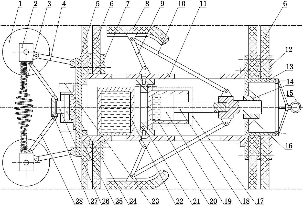
[0032] The present invention is not limited by the following implementation examples, and specific implementation manners can be determined according to the technical solutions of the present invention and actual conditions. Combine below figure 1 , 2 The present invention is described below. The positional relationship of up, down, left and right is based on the attached figure 1 determined by the layout direction.

[0033] The front end cover 13 is installed on the front end of the cylinder body 11 and connected with bolts, and the rear end cover 5 is installed on the rear end of the cylinder body 11 and connected with bolts. The rear end of cylinder body 11 is provided with rear baffle 7 and fixed by welding, the outside of said rear baffle 7 is provided with leather cup 6 and pressed with rear end cover 5, and the rear end cover 5 and rear baffle 7 are connected by bolts. Leather cup 6 is installed outside the front end cover 13 and fixes with front baffle 12, and bolt...


PUM


Abstract

The invention relates to a pipe cleaning device with an automatic brake device. The pipe cleaning device is used for pipe cleaning work. The defect that an existing speed adjusting pipe cleaning device is poor in generality in a pipe is overcome. According to the technical scheme, leather bowls are arranged at the two ends of a cylinder, one end of a connecting rod B is hinged to a brake piece, the other end of the connecting rod B is hinged to the cylinder, one end of a connecting rod C is hinged to the brake piece, the other end of the connecting rod C penetrates a groove hole of the cylinder and is hinged to a mandrel, a brake oil cylinder is arranged in the cylinder, a piston rod of the brake oil cylinder is connected with the mandrel, rollers are mounted on input shafts of hydraulic pumps, a supporting spring is arranged between the two hydraulic pumps which are arranged at the rear end of the cylinder, an oil tank is arranged in the cylinder, oil suction openings of the hydraulic pumps are connected to the oil tank, oil outlets of the hydraulic pumps are connected to a throttling valve, an oil returning opening of the throttling valve is connected to the oil tank, and the front end of the throttling valve is connected with the brake oil cylinder. A pipe cleaning device speed controller is free of an electric appliance element, safety and reliability are achieved, and the device has the high generality in the pipe.

Description

technical field [0001] The invention relates to a pipe pig with an automatic braking device, which is used for pipe pigging operations. Background technique [0002] In the process of pigging and testing oil and gas pipelines, general regulations require that the running speed of the pigging equipment is 3.5-5m / s; in order to obtain better quality of testing data, the running speed of the equipment in the pipeline is required to be lower than 5 m / s. s; electromagnetic ultrasonic testing equipment requires its operating speed to be lower than 2 m / s. The speed of the pigs changes greatly when passing through the uphill and downhill sections, curved sections, liquid accumulation, sand accumulation and fouling sections of the pipeline, and the direct use of conventional pigs cannot meet the speed control requirements. [0003] The speed control modes of existing oil and gas pipeline pigs are active control mode and passive control mode. [0004] The active control adopts the b...

Claims


Application Information

Patent Timeline
Patent Type & Authority Patents(China)
IPC IPC(8): B08B9/049B08B13/00
CPCB08B9/049B08B13/00
Inventor 梁政何虹钢张梁
Owner SOUTHWEST PETROLEUM UNIV
Learn More