
Wireless infrared remote control optogenetic system

An infrared remote control and optogenetic technology, applied in signal transmission systems, non-electrical signal transmission systems, light sources, etc., can solve the problems of large-scale mice, affect the scientificity of experiments, increase system complexity and cost, and achieve timely and accurate response

Active Publication Date: 2016-11-23
ZHEJIANG UNIV
View PDF9 Cites 7 Cited by
  • Summary
  • Abstract
  • Description
  • Claims
  • Application Information

AI Technical Summary

Problems solved by technology

However, the domestic and foreign optogenetic device production markets are still in their infancy.
[0004] At present, optogenetic devices are mostly wired devices, which use optical fiber to transmit stimulating light or require the mouse's head to be fixed, while the wireless device is too large and heavy to restrict the free movement of the mouse, so it is impossible to distinguish whether it is due to the light stimulation or the device. The restrictions have an impact on the behavior of mice, which greatly affects the scientific nature of the experiment
In addition, the use of wireless charging in wireless power supply also increases the complexity and cost of the system, making it impossible for biological experiments to be carried out in ordinary biobehavioral experiment boxes.

Method used


Image

  • Wireless infrared remote control optogenetic system
  • Wireless infrared remote control optogenetic system
  • Wireless infrared remote control optogenetic system

Examples


Embodiment Construction

[0029] The present invention will be further described below in combination with specific embodiments with reference to the accompanying drawings.

[0030] Embodiments of the present invention are as follows:

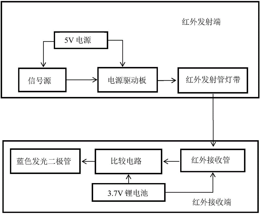
[0031] The invention uses a 0.4cm3 lithium battery of 3.7V for power supply, infrared wireless remote control, and a compact circuit board layout. All elements in the specific implementation realize the function of wirelessly controlling the precise optogenetic technology with lower product price and product complexity.

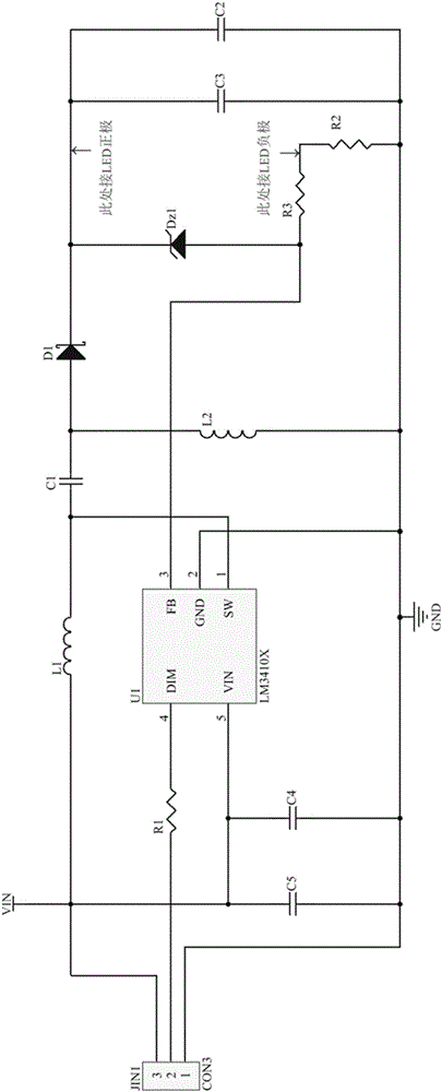
[0032] Among them, the specific implementation process is that the 5V power supply is directly supplied by a USB power adapter without an additional voltage conversion circuit, and is used as the signal source and the power supply of the power drive board respectively. The signal source depends on the situation. In this example, if the DDS signal source is used directly, the circuit board can be omitted, direct wiring, and the control signal is set to...


PUM


Abstract

The invention discloses a wireless infrared remote control optogenetic system. An infrared emitting end comprises a power supply driving board, infrared emitting tube lamp strips, a signal source and a 5V power supply; and an infrared receiving end comprises an infrared receiving pipe, a 3.7V lithium battery, a comparison circuit and blue light emitting diodes. The lighting and extinguishing of the infrared emitting tube lamp strips are controlled through controlling on-off states of the power supply by virtue of a signal source, so that the infrared emitting tube lamp strips are basically equally bright and can synchronously shine or go out; and the infrared receiving pipe is used for receiving infrared signals of infrared emitting tubes of the infrared emitting tube lamp strips, the lighting and extinguishing of blue infrared emitting diodes are controlled through the comparison circuit, and optical signals of the blue light emitting diodes are guided into biological cells through optical fibers, thereby realizing effective photic stimulation. The wireless infrared remote control optogenetic system can be remotely and wirelessly operated and controlled in an experimental box and is small in volume, high in integration level and compact in structure; and remote control signals of the signal source can be accurately and timely responded, and the infrared remote control range is wide, so that the free activities of mice in a large scope are not influenced, and the system is beneficial to the large-scale behavioral experiments.

Description

technical field [0001] The invention relates to a method and system for light stimulation of optogenetic technology, in particular to a wireless infrared remote control optogenetic system. Background technique [0002] Optogenetics technology is a method to precisely control cell activity by combining optical technology and genetic technology. Using optogenetics technology, neuroscience researchers can deeply explore the relationship between neurons in a nucleus. Position and relationship, understand the internal interaction between multiple nuclei, so as to have a clearer understanding of the structure and function of the brain structure and nervous system. In addition to conducting basic research on neuronal structure, more importantly, using this set of equipment and some animal disease models, it is possible to explore the effects of common neurological diseases such as Parkinson's disease, Alzheimer's disease, depression, etc. Brain pathological changes, understand the...

Claims


Application Information

Patent Timeline
Patent Type & Authority Applications(China)
IPC IPC(8): G08C23/04H05B33/08H05B44/00H05B45/10H05B45/20H05B45/30H05B45/325H05B45/345
CPCG08C23/04H05B45/00Y02B20/40
Inventor 龚薇斯科赵琪
Owner ZHEJIANG UNIV
Learn More