An anti-condensation reactor for dynamic in-situ spectroscopic testing

An in-situ spectroscopy and reactor technology, applied in the field of reactors, can solve the problems of weak acquisition signal intensity, beam focusing interference, etc., to prevent condensation, improve temporal and spatial resolution, and improve the effect of condensation on high-transmittance optical windows

Active Publication Date: 2019-03-05
EAST CHINA UNIV OF SCI & TECH
View PDF7 Cites 2 Cited by
  • Summary
  • Abstract
  • Description
  • Claims
  • Application Information

AI Technical Summary

Problems solved by technology

[0005] The technical problem to be solved by the present invention is to provide an anti-condensation reactor for dynamic on-site in-situ spectroscopic testing, which can be used for various dynamic in-situ in-situ spectroscopic research including Raman and other spectroscopy techniques. In a complex reaction system containing low-condensing gas, preventing condensation on the inside of the optical window can avoid the problems of beam focus interference, energy attenuation, and weak signal intensity caused by condensed droplets, so as to improve dynamic in-situ Temporal and spatial resolution of experiments

Method used


Image

  • An anti-condensation reactor for dynamic in-situ spectroscopic testing
  • An anti-condensation reactor for dynamic in-situ spectroscopic testing
  • An anti-condensation reactor for dynamic in-situ spectroscopic testing

Examples


Embodiment 1

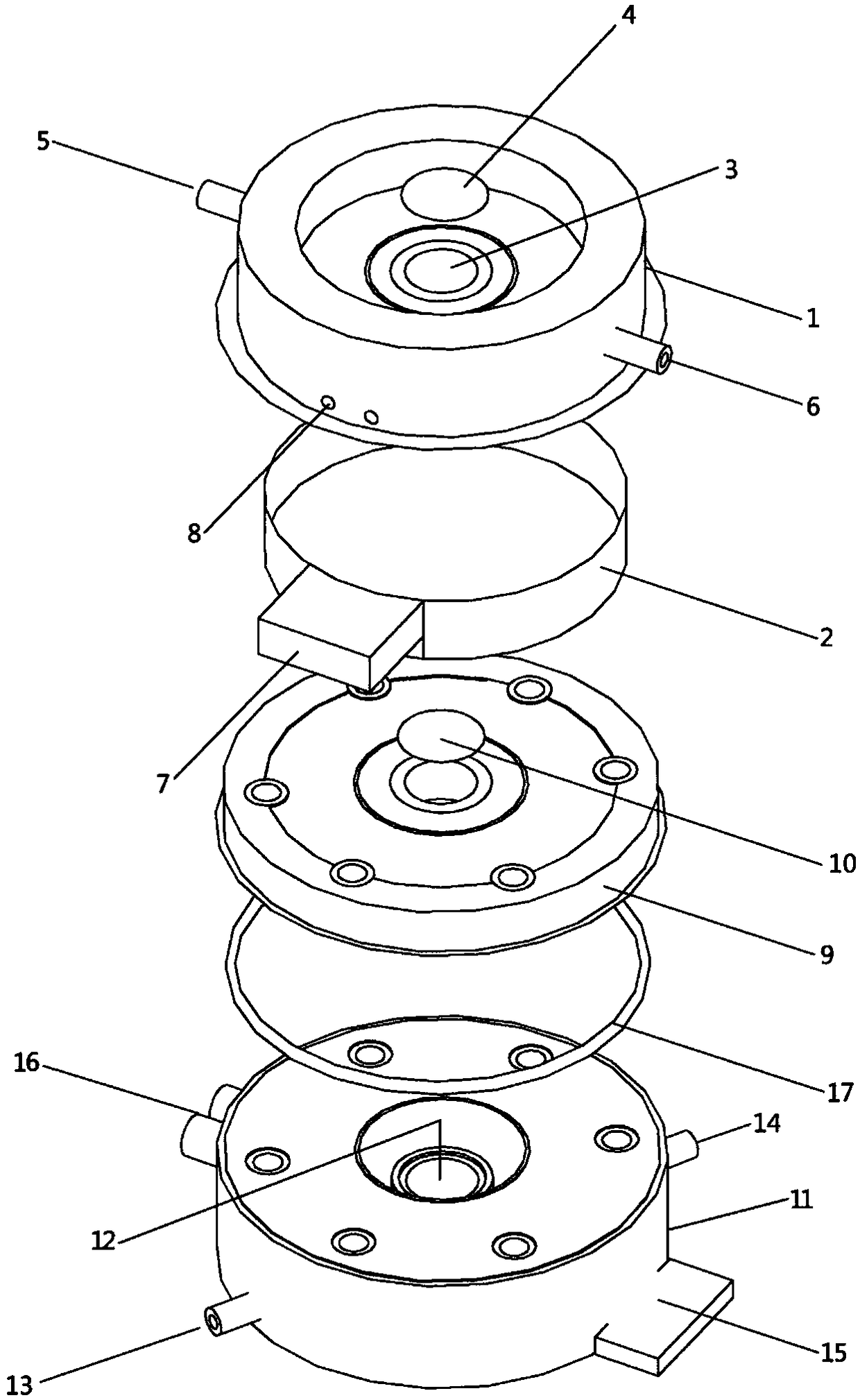
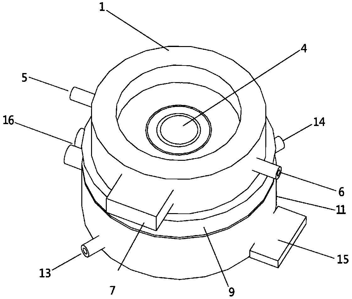
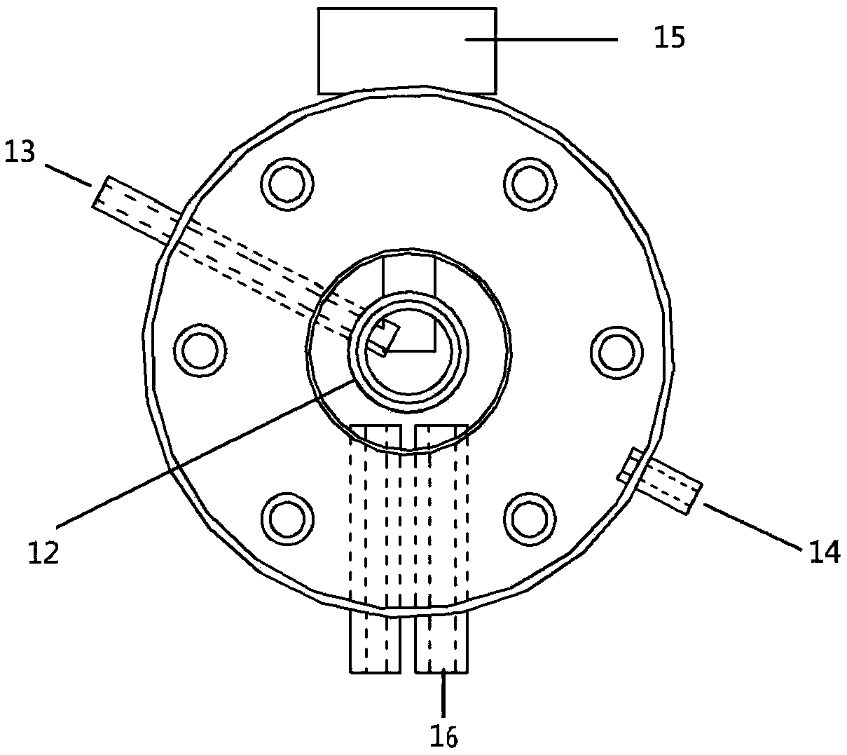
[0036] In this example, using figure 1 Shown is a dynamic in situ spectroscopic test using an anti-condensation reactor. The reactor main body 11 and the reactor cover 9 are made of stainless steel. The reactor main body 11 has a diameter of 62 mm and a height of 20 mm. The internal sample pool 12 has a diameter of 24 mm and a depth of 16 mm. 5mm. O-ring 17 has an outer diameter of 43.5mm and an inner diameter of 38.5mm. Both the high-transmittance optical window 4 in the low-pressure area and the high-transmission optical window 10 in the reactor have a diameter of 17 mm and a thickness of 1 mm. The outer diameter of the cover 1 in the low-pressure area is 54 mm and the wall thickness is 3 mm. A light hole 3 with a diameter of 16mm is provided at the center of the low-pressure area cover 1, and the diameter of the annular heating belt 2 is 30mm.

[0037]Under the indoor condition of humidity 90%, temperature 35 ℃, carry out the Raman (Raman) field dynamic in-situ experimen...

Embodiment 2

[0039] The anti-condensation type reactor adopted in this embodiment is the same as that in Embodiment 1. Under the conditions of 260°C and 2MPa, Fe-based Fischer-Tropsch synthesis was used to prepare high value-added chemicals. The catalyst samples were first filled in the sample cell 12 with quartz wool pads. After the samples were compacted and leveled, the reactor cover 9 and The O-ring 17 seals the reactor main body 11 and the reactor cover 9 with bolts and nuts. Then cover the low-pressure zone cover 1, feed the non-condensable inert gas high-purity argon into the gas delivery inlet 5 of the low-pressure zone, then vacuumize the low-pressure zone to a vacuum degree of 0.08MPa, and heat the low-pressure zone to 200°C. The cooling water channel 16 is connected to an external circulating low-temperature tank, and water is used as cooling liquid to assist in temperature control. Fix the installed reactor on the detection platform, adjust the position of the lens and the pla...


PUM


Abstract

The invention relates to an anti-condensation type reactor for a dynamic site in-situ spectrum test. A low pressure area mainly composed of a low pressure area cover and a heating belt is installed on the reactor. A light hole with a high-transmittance optical window plate is formed in the center of the upper surface of the low pressure area cover. A gas conveying inlet and a gas conveying outlet are formed in the side wall of the low pressure area cover. The heating belt is sleeved with the low pressure area cover. A reactor cover is connected with the low pressure area cover to form a low pressure area closed space. A light hole with a high-transmittance optical window plate is formed in the center of the upper surface of the reactor cover. The high-transmittance optical window plate of the reactor and the high-transmittance optical window plate of the low pressure area are located on the same light path. A sample pool is arranged at the center of a reactor body. A raw material conveying channel is arranged at the bottom of the sample pool. A product outlet channel is arranged on the side wall of the reactor body. A cooling water channel is arranged on the reactor body and / or the reactor cover. The problems of beam focusing interference, energy attenuation and weak collected signal strength caused by condensed liquid drops can be avoided, and the time-space definition of a dynamic site in-situ experiment is improved.

Description

technical field [0001] The invention relates to a reactor, in particular to an anti-condensation reactor for dynamic on-site in-situ spectrum testing. Background technique [0002] Modern molecular spectroscopy has been widely used in physics, chemistry, biology and other fields. Especially in the field of chemistry and chemical engineering, in situ and dynamic in situ (Operando) technologies have broadened the development space in the field of catalysis. In situ reactors developed based on related research are also becoming more and more mature. [0003] Taking Raman spectroscopy as an example, this technology has enabled in-situ research under harsh conditions (high temperature and high pressure). However, the scope of application of this type of reactor for spectral testing is still not wide. For complex chemical reaction systems with low-condensing gases, the gas components are likely to condense at the high-transmittance optical window with the flow of mass transfer i...

Claims


Application Information

Patent Timeline
Patent Type & Authority Patents(China)
IPC IPC(8): G01N21/15
CPCG01N21/15
Inventor 韩一帆徐晶张俊张征湃辛玮玥
Owner EAST CHINA UNIV OF SCI & TECH
Why Eureka
Try Eureka