Iron-based powder core magnet and manufacturing method thereof

A manufacturing method, iron-based powder technology, applied in the direction of permanent magnet manufacturing, inductor/transformer/magnet manufacturing, magnetic objects, etc. Mass production and other issues, to achieve mass production, increase insulation, improve hardness and wear resistance

Active Publication Date: 2016-11-09
SHENZHEN SUNLORD ELECTRONICS
View PDF7 Cites 0 Cited by
  • Summary
  • Abstract
  • Description
  • Claims
  • Application Information

AI Technical Summary

Problems solved by technology

This treatment method is a solid-liquid mixing operation, which is not suitable for mass production, and it is processed in a liquid environment, which cannot guarantee the uniformity of the treatment results after treatment, and it is easy to cause Al in the drying process after treatment. 2 o 3 In the case where the insulating layer is separated from the material, this treatment method does not mention the problem of the bonding strength between the insulating layer and the magnetic powder
[0005] Patent No. CN1373481A and Patent No. CN1518011A respectively use organic insulating adhesive to improve insulation performance. Although the operation is simple and the bonding effect is good, the heat resistance is poor.

Method used


Image

  • Iron-based powder core magnet and manufacturing method thereof

Examples


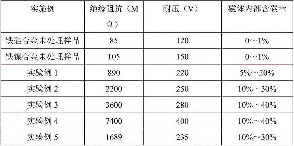
experiment example 1

[0028] In this experimental example, ethyl acetate + methanol is selected as the carburizing agent, which is equivalent to an organic carbon compound with 4 carbon atoms in a single molecule. Control the proportion of carburizing agent so as to realize the control of carbon potential at 0.5%±0.1%.

[0029] First, load 500pcs of iron-silicon alloy soft magnetic material with length*width*height=2.5*2.15*0.9mm with stainless steel mesh (the aperture size of the stainless steel mesh is slightly smaller than the length and width of the magnet) and fix it with iron wire to prevent the magnet from leaking .

[0030] Secondly, put the loaded 500pcs iron-silicon alloy soft magnetic material in the prepared closed space that can be heated and exchange gas to carry out the adsorption of organic carbon source ethyl acetate + methanol. The specific operation is: first put the sample into the equipment, then pass in the organic carbon source steam, and after the internal air is exhausted, t...

experiment example 2

[0034] In this experimental example, acetone+methanol is selected as the carburizing agent, which is equivalent to an organic carbon compound containing 3 carbon atoms in a single molecule. Control the proportion of carburizing agent so as to realize the control of carbon potential at 0.7%±0.1%.

[0035] First, load 500pcs of iron-silicon alloy soft magnetic material with length*width*height=2.5*2.15*0.9mm with stainless steel mesh (the aperture size of the stainless steel mesh should be slightly smaller than the length and width of the magnet) and fix it with iron wire to prevent the magnet from leaking .

[0036] Secondly, put the loaded 500pcs iron-silicon alloy soft magnetic material in the prepared closed space that can be heated and exchange gas for adsorption of organic carbon source acetone+methanol. The specific operation is: first put the sample into the equipment, then pass in the organic carbon source steam, and after the internal air is exhausted, the internal pr...

experiment example 3

[0040] In this experimental example, propane+methanol is selected as the carburizing agent, which is equivalent to an organic carbon compound containing 3 carbon atoms in a single molecule. Control the proportion of carburizing agent so as to realize the control of carbon potential at 0.6%±0.1%.

[0041] First, load 500pcs of iron-nickel alloy soft magnetic material with length*width*height=2.5*2.15*0.9mm with stainless steel mesh (the diameter of the stainless steel mesh should be slightly smaller than the length and width of the magnet) and fix it with iron wire to prevent the magnet from leaking .

[0042] Secondly, put the loaded 500pcs iron-nickel alloy soft magnetic material in the prepared closed space that can be heated and exchange gas for adsorption of organic carbon source propane+methanol. The specific operation is: first put the sample into the equipment, then pass in the organic carbon source steam, and after the internal air is exhausted, the internal pressure ...


PUM

PropertyMeasurementUnit
depthaaaaaaaaaa

Abstract

The invention discloses an iron-based powder core magnet and a manufacturing method thereof. The manufacturing method includes the following steps of S1, placing the iron-based powder core magnet in an organic carbon source steam atmosphere, processing the iron-based powder core magnet for 1 hour to 5 hours under the conditions that the temperature T1 is higher than 100 DEG C but lower than or equal to 500 DEG C, the intensity of pressure is 1-20 MPa and the carbon potential is controlled to be 0.4-2.0%, and making the surface of the iron-based powder core magnet adsorb active carbon atoms; taking out the iron-based powder core magnet after waiting for the iron-based powder core magnet to be cooled to room temperature, then placing the iron-based powder core magnet in an inert gas atmosphere, processing the iron-based powder core magnet for 1 hour to 6 hours under the condition that the temperature T2 is higher than 500 DEG C but lower than or equal to 900 DEG C, and making the adsorbed active carbon atoms on the surface permeate into the iron-based powder core magnet; S2, immersing the iron-based powder core magnet into fast quenching oil and completing quenching under the condition of 70+ / -10 DEG C; and S3, rinsing the iron-based powder core magnet, and then performing drying treatment operation. The obtained iron-based powder core magnet has higher insulation and pressure-tolerant characteristics and the manufacturing method can realize mass production.

Description

【Technical field】 [0001] The invention relates to an iron-based powder core magnet and a manufacturing method thereof. 【Background technique】 [0002] Iron-based powder core magnet soft magnetic materials are widely used in transformers and power transformers because of their higher saturation flux than ferrite, wide operating temperature range (-55 to 200°C), low temperature coefficient and low cost. The magnetic core of the inductor. Compressed iron-based powder core magnets have no insulating medium inside, resulting in low insulation resistance and low withstand voltage of such cores, which seriously hinders the application of inductors and transformers with iron-based alloys as magnetic cores in certain fields. At present, the schemes on how to improve the insulation and voltage resistance performance of iron-based powder core magnets mainly include phosphoric acid oxidation, surface coating with inorganic materials, surface coating with organic materials, etc. [000...

Claims


Application Information

Patent Timeline
Patent Type & Authority Applications(China)
IPC IPC(8): C23C8/22C21D1/18H01F1/147H01F41/02
CPCC21D1/18C21D2201/00C21D2221/10C23C8/22H01F1/14766H01F41/026
Inventor 尚玉黎侯勤田曾艳军吴锦超王其艮蒋家军秦浩
Owner SHENZHEN SUNLORD ELECTRONICS
Why Eureka
Try Eureka