
Semi-automatic 3D spherical milling-grinding machine

A kind of milling machine, semi-automatic technology, applied in the direction of spherical grinding machine, grinding frame, grinding machine tool parts, etc., can solve the problems of not being able to fit the equipment head tightly, affecting the strength of the pipeline, and large grinding volume, etc., to achieve Save manpower and time cost, reasonable structure design, stable processing effect

Active Publication Date: 2016-08-31
CHINA NAT OFFSHORE OIL CORP +3
View PDF5 Cites 0 Cited by
  • Summary
  • Abstract
  • Description
  • Claims
  • Application Information

AI Technical Summary

Problems solved by technology

The disadvantage of this construction method is that there are many foam glass tiles to be processed, and the amount of on-site grinding is large; there are many joints, resulting in poor thermal insulation performance; the inner and outer surfaces are cylindrical instead of spherical, so they are sealed with the equipment after installation. There are gaps between the heads, which will affect the insulation and anti-corrosion effects, especially for cryogenic insulation. Once there is moisture in the gaps, the moisture will freeze after the pipeline runs, which will affect the pipeline strength.
Therefore, the foam glass processed by the traditional process has a large workload during processing, and cannot be closely attached to the equipment head, and the cost is relatively high

Method used


Image

  • Semi-automatic 3D spherical milling-grinding machine
  • Semi-automatic 3D spherical milling-grinding machine

Examples


Embodiment Construction

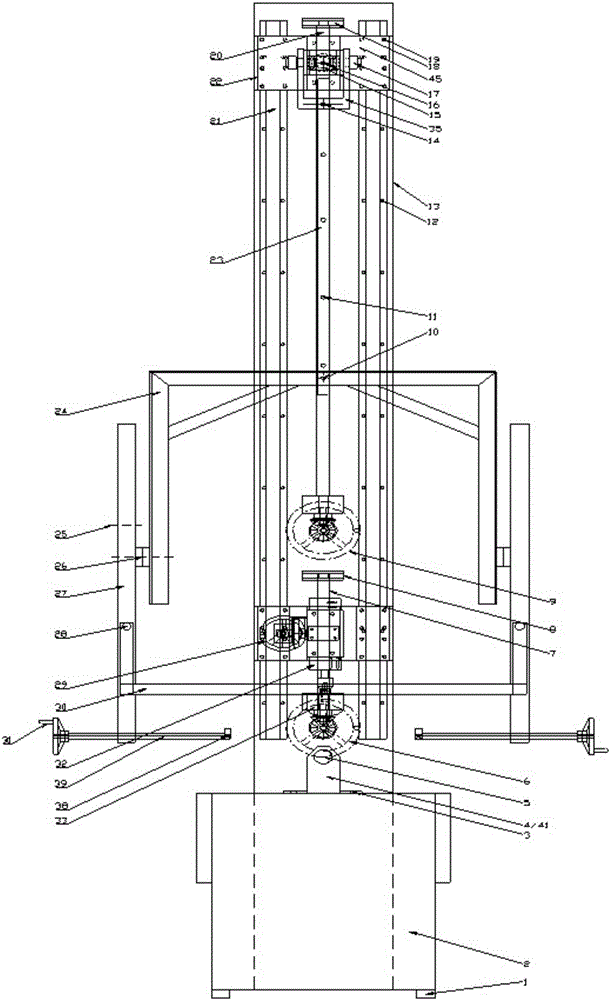
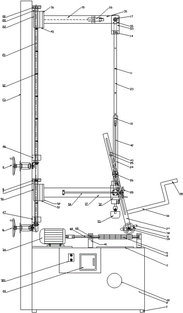
[0024] Such as figure 1 , figure 2 As shown, the semi-automatic 3D spherical milling machine of the present invention is characterized in that it is provided with: a support box 2, and the top surface of the support box is respectively connected with a grinding wheel rod motor 34, a front grinding wheel seat 4, a rear Wheel base 41, a leaker 3;

[0025] The support box 2 is a hollow box, and the leaker 3 communicates with the inside of the support box; the rotating shaft 48 of the grinding wheel rod motor 34 is connected with the grinding wheel rod bearing 49 that passes through the front grinding wheel seat 4 and the rear grinding wheel seat, and the grinding wheel rod A grinding wheel rod 5 is sleeved on the rotating shaft 48 of the motor; the outer wall of the support box 2 is connected with the main grinding wheel motor switch 321 and a grinding wheel rod motor switch 44 by bolts and offers a dust suction port 40, which is connected to the vacuum cleaner Connected, the ...


PUM


Abstract

The invention provides a semi-automatic 3D spherical milling-grinding machine. The machine is characterized in that a grinding wheel rod motor, a front grinding wheel seat, a rear grinding wheel seat and a discharging device are connected to the top surface of a supporting box body; the grinding wheel rod motor is sleeved with a grinding wheel rod; a dust absorbing port 40 and a vertical base plate are arranged on the sidewall of the supporting box body; guide rails are arranged on the vertical base plate, and a motor support lifting handwheel connected with a motor support power screw is connected to the vertical base plate; the motor support power screw can drive a motor support; a main shaft lifting handwheel is arranged on the vertical base plate and is used for driving the main shaft power screw so as to drive a main shaft supporting arm; the main shaft supporting arm arranged on a guide rail upper bearing connecting plate is connected with a horizontal rotating shaft; the horizontal rotating shaft is connected with a vertical swinging frame which is connected with a hoisting rod; the hoisting rod is connected with a secondary frame which is connected with a secondary telescoping frame, and the secondary telescoping frame is connected with a clamping frame and lead screws; each lead screw is connected with a hand wheel and a clamping head. With the adoption of the machine, the cutting of the inner surface and the outer surface of foam glass and the spherical cutting of the double-radius foam glass can be synchronously carried out, so that the quality of a finished product is high.

Description

technical field [0001] The invention relates to a semi-automatic 3D spherical milling machine. Background technique [0002] At present, in the construction process of LNG, the thermal insulation construction of process equipment is one of the most important links. Due to the large size of the equipment, there are many functional accessories on it, and the shapes of each part are different, the thermal insulation construction requires that the foam glass should be closely attached to the irregular surface. and strength properties. Among these irregular surfaces, the equipment head is one of the largest parts, and its structure is as follows: the upper part is a single-radius spherical top, and the lower part connected to the equipment cylinder is a double-radius sphere. At present, for the thermal insulation installation of the equipment head, it is generally cut into tiles as small as possible by machine, and then polished and installed on site. The disadvantage of this ...

Claims


Application Information

Patent Timeline
Patent Type & Authority Applications(China)
IPC IPC(8): B24B11/00B24B27/00B24B41/06B24B47/20B24B41/02B24B55/06
CPCB24B11/00B24B27/0076B24B41/02B24B41/06B24B47/203B24B55/06
Inventor 李文义张锦宝张灿辛培刚刘拥军赵怀岗韩少宁杨风艳薛士辉杨海军李祥民吴海忠鞠学国刘鹏
Owner CHINA NAT OFFSHORE OIL CORP
Learn More