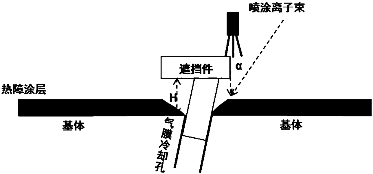
A method for plugging surface micropores during thermal spraying
A surface microporous, thermal spraying technology, applied in the direction of coating, fusion spraying, metal material coating process, etc., can solve the problem of gas film hole blockage, etc., and achieve the effect of easy removal
- Summary
- Abstract
- Description
- Claims
- Application Information
AI Technical Summary
Problems solved by technology
Method used
Image

Examples
Embodiment 1
[0025] The MCrAlY bonding layer and TBC ceramic top layer were prepared by atmospheric plasma spraying (APS) to form a typical thermal barrier coating (TBC) structure. The spraying parameters are shown in Table 1. 304 stainless steel was used as the base material in this experiment. Before spraying, pre-treat the substrate, sand the substrate with fine sandpaper, and then scrub the substrate with acetone. The MCrAlY type coating layer is used as the high temperature oxidation resistance and TBC transition layer, and the coating material is gas atomized Ni-based superalloy Ni-23Co-20Cr-8.5Al-5.0Ta-0.6Y (Sulzer-Metco Amdry 997) powder. The ceramic coating uses 8wt% yttrium oxide (Y 2 o 3 ) stabilized zirconia 8YSZ (Metco 204B-NS, Sulzer Metco Inc., New York, USA), particle size distribution: -75+45 μm, the powder is an agglomerated powder with a hollow spherical structure (HOSP).
[0026] Table 1 Parameters of APS sprayed bonding layer and ceramic layer
[0027]
[0028] ...
Embodiment 2
[0034] The MCrAlY bonding layer and the TBC ceramic top layer were prepared by atmospheric plasma spraying (APS) to form a typical thermal barrier coating (TBC) structure, and the coating preparation was the same as in Example 1.
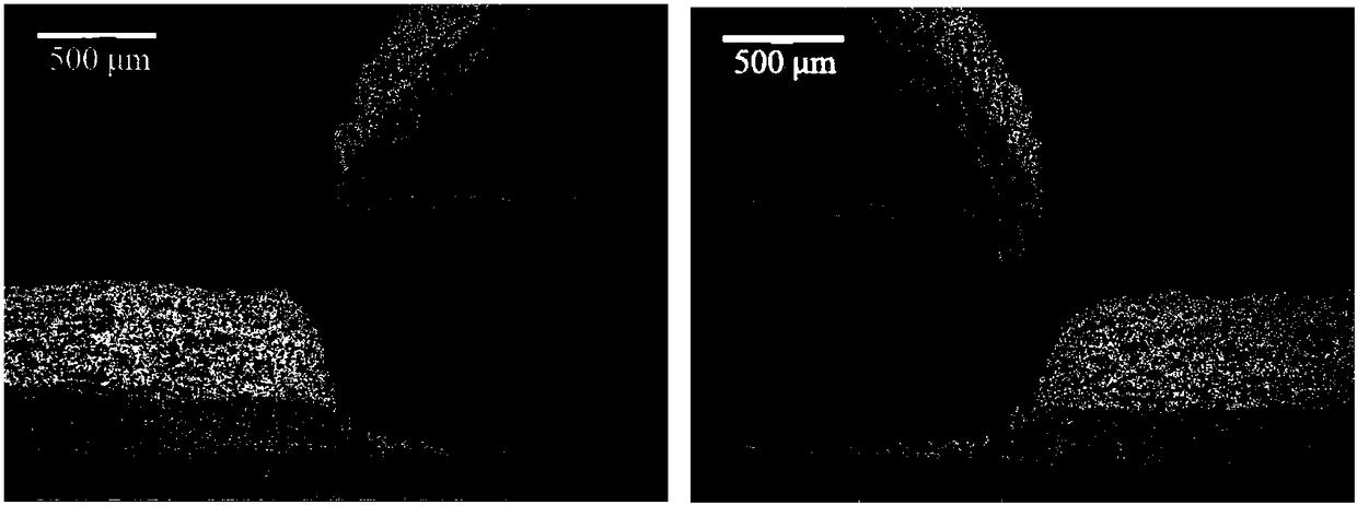
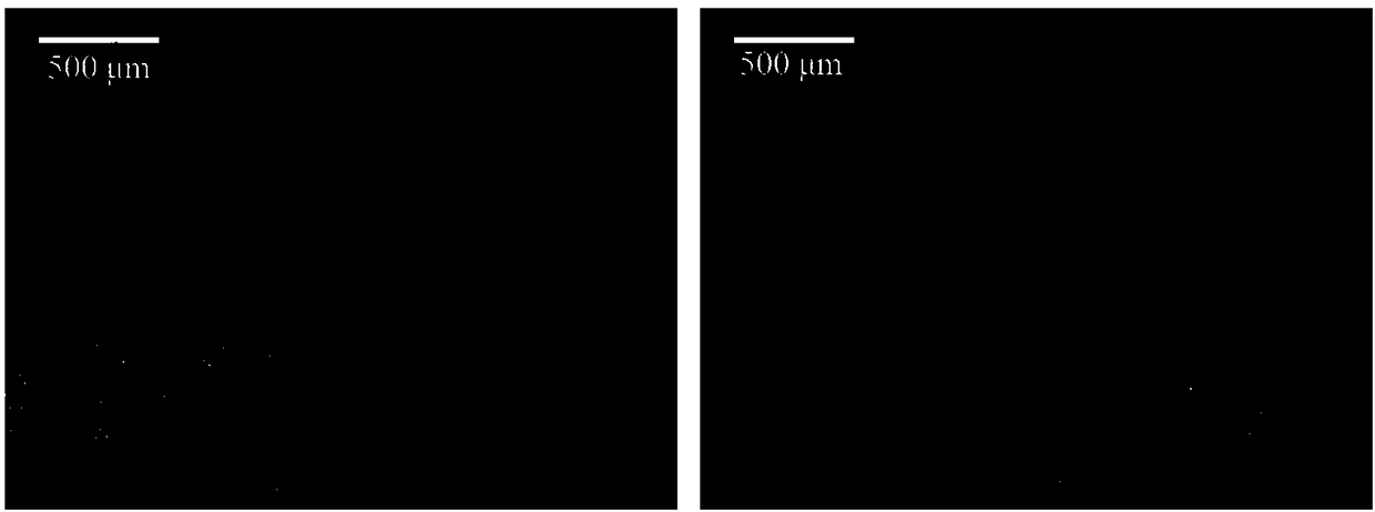
[0035] The shape of the occluder is at an oblique angle of 45°, the occlusion heights are 1, 2, and 3mm respectively, and the spraying direction is at an angle of 30° to the normal line of the substrate. The coating deposition characteristics under the shaded area and the unshielded area are as follows: image 3 middle Figure 3a , Figure 3b and image 3 c and shown in Table 4 and Table 5. It can be seen that when the spraying direction is changed to an angle of 30°, the coating morphology on the left and right sides of the same shield is quite different. The topography of the coating edge on the left appears steeper compared to the one on the right. The coating morphology changes on the same side of the substrate under different shading heigh...
PUM
| Property | Measurement | Unit |
|---|---|---|
| particle size distribution | aaaaa | aaaaa |
Abstract
Description
Claims
Application Information
 - R&D
- Intellectual Property
- Life Sciences
- Materials
- Tech Scout
- Unparalleled Data Quality
- Higher Quality Content
- 60% Fewer Hallucinations
Browse by: Latest US Patents, China's latest patents, Technical Efficacy Thesaurus, Application Domain, Technology Topic, Popular Technical Reports.
© 2025 PatSnap. All rights reserved.Legal|Privacy policy|Modern Slavery Act Transparency Statement|Sitemap|About US| Contact US: help@patsnap.com