LED light power supply assembly and LED lamp

A technology for LED lamps and photoelectric power sources, applied in the directions of light sources, lamp shades, circuit layouts, etc., can solve the problems of heavy weight, large proportion of volume and weight of LED photoelectric power source assemblies, and complex heat transfer paths.

Inactive Publication Date: 2016-07-27
NANKER GUANGZHOU SEMICON MFG
View PDF7 Cites 2 Cited by
  • Summary
  • Abstract
  • Description
  • Claims
  • Application Information

AI Technical Summary

Problems solved by technology

like figure 1 Shown is the schematic diagram of the LED light power supply assembly with the wind guide cover of the utility model patent No. ZL201120521413.6 previously applied by the applicant, which is fixedly connected with the radiator, the light source substrate and the fan with the radiator as the center. The air guide cover is fixedly connected with the fan or heat sink and the power supply box and the fan or heat sink. The heat sink occupies a large proportion of the volume and weight of the entire LED light power supply assembly, resulting in a large volume of the LED light power supply assembly. Heavy weight, space occupation, and high cost. The LED light source assembly first conducts heat from the light source substrate to the radiator, and then the heat is taken away by the cooling fan. The heat transfer path is complicated.

Method used


Image

  • LED light power supply assembly and LED lamp
  • LED light power supply assembly and LED lamp
  • LED light power supply assembly and LED lamp

Examples


Embodiment 1

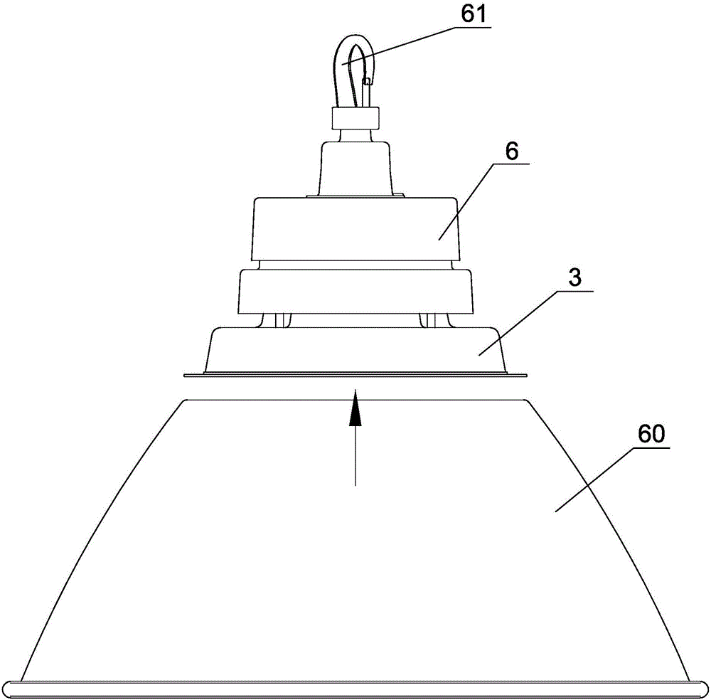
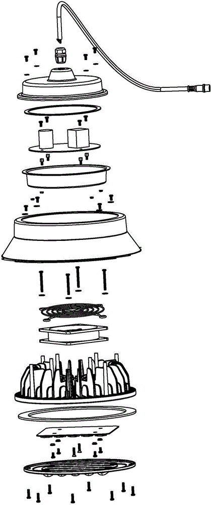
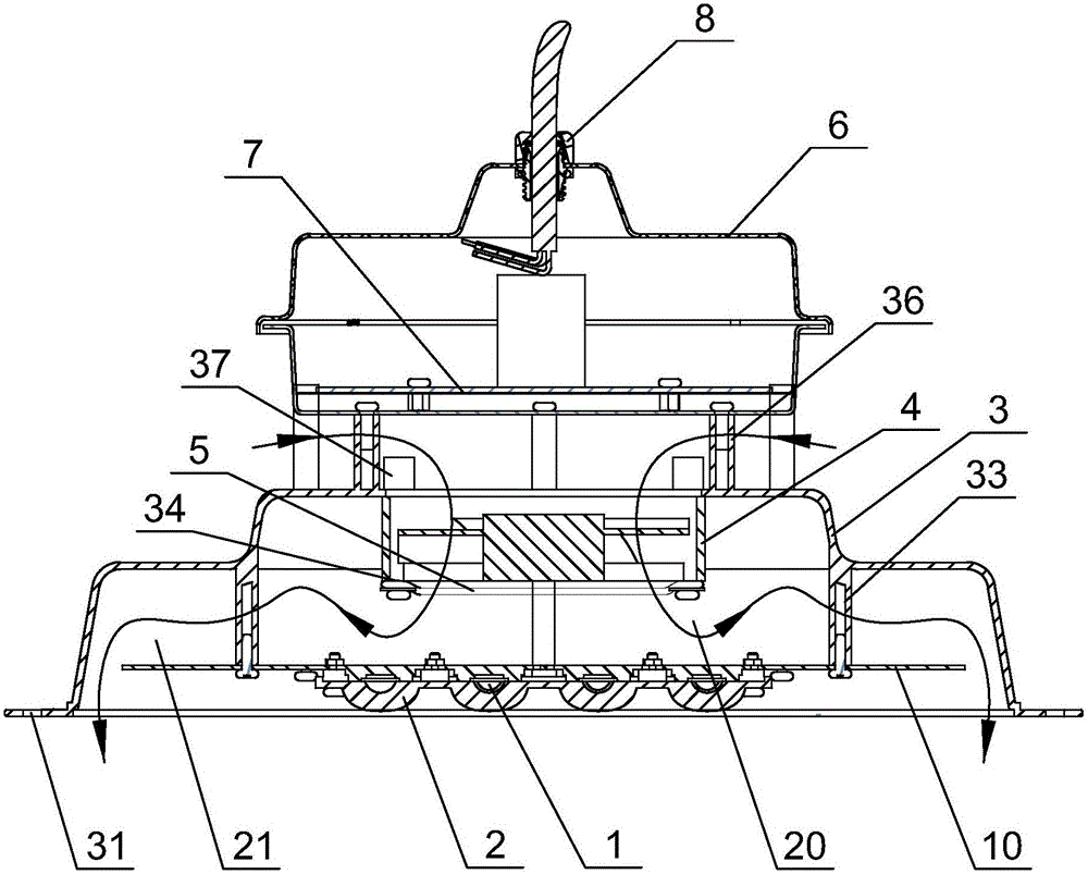
[0047] Such as figure 2 , Figure 7 ~ Figure 9 As shown, the LED optical power supply assembly of this embodiment includes a heat dissipation light source board 10 with a plurality of LED chips 1, a wind deflector 3, a heat dissipation fan 4, a power supply box assembly 6, and a driver located in the power supply box assembly 6. A circuit board assembly 7, a power supply harness assembly 8 for connecting the drive circuit board assembly 7 and the heat dissipation light source board 10 electrically, the LED light power supply assembly does not have a heat sink, and the wind guide The cover 3 is stepped and encloses a large-diameter cavity and a small-diameter cavity. The heat dissipation light source plate 10 is fixedly connected to the air deflector 3 and is located in the large-diameter cavity of the air deflector 3. The fan 4 is fixedly connected to the air deflector 3, the power supply box assembly 6 is fixedly connected to the air deflector 3 and is located above the air de...

Embodiment 2

[0050] Such as image 3 , Figure 7 , Figure 8 As shown, the difference between the LED optical power supply assembly of this embodiment and the first embodiment is that: in this embodiment, the LED optical power supply assembly further includes an extension stud 11, and the heat dissipation fan 4 is located in the air guide. Above the outside of the cover 3, the cooling fan 4 is fixedly connected to the fan outer pillar 37, and the extension stud 11 is connected to the power box pillar 36 to extend the length of the power box pillar 36 to adapt to The space brought by the external heat dissipation fan increases. Without changing the structure of the air deflector 3, it is convenient for the power supply box assembly 6 to be directly installed and fixed on the extension stud 11, so that the air deflector 3 It has a wide range of applications, reduces the types of accessories, and facilitates inventory; outside air enters from the annular tuyere, flows through the diversion area...

Embodiment 3

[0053] Such as Figure 4 , Figure 7 ~ Figure 9 As shown, the difference between the LED optical power supply assembly of this embodiment and the first embodiment is that: in this embodiment, the LED optical power supply assembly further includes a wind deflector 9, and the center of the wind deflector 9 is provided An air outlet, the air deflector 9 is fixedly connected to the air deflector 3 and the edge shields the front of the annular air outlet, so that the air flowing through the annular air outlet is diverted from the air outlet in the center of the air deflector 9 In and out, the inside of the air deflector 3 is provided with an air deflector pillar 32 supporting and fixing the air deflector 9; outside air enters from the air outlet in the center of the air deflector 9, flows through the annular air outlet and then turns into The diversion area 21 and the vortex flow in the vortex area 20 enters the heat dissipation fan 4, and the air flowing out of the heat dissipation ...


PUM


Abstract

The invention discloses an LED light power supply assembly and an LED lamp. The LED light power supply assembly comprises a heat dissipation light supply plate (10) with LED chips (1), a wind scooper (3), a heat dissipation fan (4), a power supply box component (6), a drive circuit board component (7) and a power supply harness component (8), and is not provided with a radiator, wherein the wind scooper (3) is step-shaped; the heat dissipation light supply plate (10) is fixedly connected with the wind scooper (3), and is positioned in a large-diameter cavity of the wind scooper (3); the heat dissipation fan (4) is fixedly connected with the wind scooper (3); the power supply box component (6) is fixedly connected with the wind scooper (3), and is positioned above the wind scooper (3) and the heat dissipation fan (4); an air flow space is arranged between the power supply box component (6) and the heat dissipation fan (4); an annular air vent is formed between the side walls of the heat dissipation light supply plate (10) and the wind scooper (3); a flow guide zone (21) is formed between the back surface of the heat dissipation light supply plate (10) and the side wall and the back wall of the large-diameter cavity of the wind scooper (3); and an eddy zone (20) is formed between the back surface of the heat dissipation light supply plate (10) and the back wall of a small-diameter cavity of the wind scooper (3).

Description

Technical field [0001] The present invention relates to an LED light power supply assembly; the present invention also relates to an LED lamp including the LED light power supply assembly. Background technique [0002] LED has the advantages of high luminous efficiency, power saving and long life, and its application is more and more extensive. LEDs are used in daily lighting. In order to meet the illumination requirements, multiple power LEDs are generally used in one lamp. Therefore, the heat dissipation of LEDs has become an important factor affecting the use status and life of LED lamps, especially for high-power LED lamps. The heat dissipation problem has become a technical bottleneck affecting its widespread application. Traditional LED lamps are passive heat dissipation, that is, heat is dissipated through the heat sink of the radiator or similar devices. In order to improve the heat dissipation effect, it is necessary to increase the heat dissipation area as much as poss...

Claims


Application Information

Patent Timeline
Patent Type & Authority Applications(China)
IPC IPC(8): F21K9/20F21V29/67F21V23/00F21V5/04F21V3/00F21Y115/10
CPCF21V23/003F21V3/00F21V5/04
Inventor 吴俊纬
Owner NANKER GUANGZHOU SEMICON MFG
Why Eureka
Try Eureka