
Photoluminescent diamond detection method and photoluminescent diamond detection device

A technology of photoluminescence and detection devices, which is applied in the field of photoluminescence diamond detection methods and devices, can solve problems such as harsh conditions, large measurement spots, and easy to get dirty, and achieve the advantages of avoiding measurement errors, high detection efficiency, and strong practicability Effect

Inactive Publication Date: 2016-07-20
BIAOQI ELECTRONICS TECH
View PDF9 Cites 7 Cited by
  • Summary
  • Abstract
  • Description
  • Claims
  • Application Information

AI Technical Summary

Problems solved by technology

Disadvantages of photoluminescence: usually only qualitative analysis can be done, not quantitative analysis; if low temperature test is done, liquid helium cooling is required, and the conditions are relatively harsh; non-radiative recombination deep-level defect centers cannot be reflected
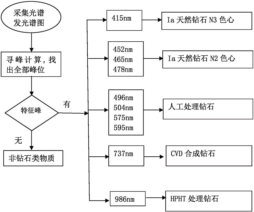
[0006] At present, UV-visible absorption spectrum and Raman spectrum are mainly used for measurement. UV-visible absorption spectrum is used to measure peaks such as 415, 452nm, 465nm, and 478nm. Compared with the film, it is easy to get dirty, which will easily lead to measurement errors, and the measurement spot is too large, which is difficult to measure for small particle samples; Raman spectroscopy can determine whether it is a diamond, and some synthetic diamonds, but it cannot determine whether it is a type Ia natural diamond. Usually it takes 2 equipment or even more equipment, and the price is expensive

Method used


Image

  • Photoluminescent diamond detection method and photoluminescent diamond detection device
  • Photoluminescent diamond detection method and photoluminescent diamond detection device

Examples


Embodiment Construction

[0037] The present invention will be described in further detail below in conjunction with the accompanying drawings and specific embodiments.

[0038] Such as figure 1 As shown, the specific embodiment of the present invention is a photoluminescence diamond detection device, including a light source 1, a workbench 2, an array detector 3, and a data processing terminal 4, and the sample to be inspected is placed on the workbench 2 5. The wavelength of the light source 1 is monochromatic light or mixed light with a wavelength less than or equal to 410nm. The light emitted by the light source 1 is irradiated onto the sample 5 to be tested, so that the sample 5 to be tested can obtain energy and generate excitation to cause light emission. After the light is injected into the array detector 3 for detection, the light emitted by the sample to be tested after excitation includes fluorescence, Raman light and hole luminescence, and then the photon information of the luminescent lig...


PUM

PropertyMeasurementUnit
Wavelengthaaaaaaaaaa

Abstract

The invention discloses a photoluminescent diamond detection device. The photoluminescent diamond detection device comprises a light source, a workbench, an array detector and a data processing terminal. A to-be-detected sample is placed on the workbench. The light source is monochromatic light or hybrid light with the wavelength of smaller than or equal to 410nm. The light source emits the light to the to-be-detected sample, the to-be-detected sample acquires energy and is excited to emit light, luminous light rays are emitted into the array detector to be detected, photon information of the luminous light rays is converted into an electric signal according to wavelength sequence, the electric signal is converted into a digital signal through analog-digital conversion, the digital signal is transmitted to the data processing terminal to form a real-time photoluminescent spectrogram. The photoluminescent diamond detection device has the advantages that multiple peak positions can be measured at a time by a photoluminescence method, the problems such as whether the to-be-detected sample is a diamond, a compound diamond or a natural diamond or not are solved, detection sensitivity and detection speed are high, and detection cost is low.

Description

technical field [0001] The invention relates to the field of diamond detection, in particular to a photoluminescent diamond detection method and device. Background technique [0002] Photoluminescence refers to the phenomenon that an object relies on an external light source for irradiation to obtain energy and generate excitation to cause light emission. It roughly passes through three main stages: absorption, energy transfer, and light emission. The absorption and emission of light both occur between energy levels. transitions through the excited state. Energy transfer is due to the motion of excited states. Photoluminescence can be induced by ultraviolet radiation, visible light, and infrared radiation. such as phosphorescence and fluorescence. [0003] Photoluminescence Spectroscopy (PL spectrum for short), refers to the material under the excitation of light, electrons transition from the valence band to the conduction band and leave holes in the valence band; electr...

Claims


Application Information

Patent Timeline
IPC IPC(8): G01N21/63G01N21/64G01N21/65
CPCG01N21/63G01N21/6402G01N21/65G01N2021/655
Inventor 宋光均
Owner BIAOQI ELECTRONICS TECH
Learn More