
Inner groove screw and plunger coaxial injection molding machine

An injection molding machine and internal screw groove technology, which is applied in the field of material molding equipment, can solve the problems of drag, homogenization, and mixing that are not particularly strong, increase the complexity and difficulty of the overall system, increase the volume of the machine and the number of parts, etc. problems, to achieve the effect of increased shearing action, small axial temperature difference, and low production cost

Active Publication Date: 2017-11-28
ANHUI HUATENG AGRI TECH CO LTD
View PDF5 Cites 0 Cited by
  • Summary
  • Abstract
  • Description
  • Claims
  • Application Information

AI Technical Summary

Problems solved by technology

Due to the need for two sets of barrels (one for plasticizing and one for injection), the volume of the machine and the number of parts are increased, so the manufacturing cost is high. In addition, two sets of heating systems are required to heat the screw plasticizing system and the plunger respectively. Injection system heats up, increasing overall energy consumption
[0005] The traditional reciprocating screw injection molding machine cancels the injection plunger. The screw has two functions of plasticization and injection at the same time. Injection, which requires special consideration in screw design and connection transmission, greatly increases the complexity and difficulty of the overall system, and increases the cost of manufacturing, use and maintenance. Moreover, when plasticizing, due to the shaft of the screw Moving to the direction, the axial temperature difference formed by the melt temperature is relatively large, and it is difficult to overcome
[0006] Moreover, the traditional injection molding machine with a screw also has an obvious shortcoming, that is, its screw groove is located on the outer circumference of the screw rod, and this structure will cause two kinds of problems: one is that the screw rod and the machine barrel have a negative impact on the material in the screw groove. The dragging, homogenizing and mixing effects are not particularly strong. The second is that the screw groove is on the outer circumference of the screw, and the electric heating ring is installed outside the barrel, so the heat is lost quickly and the thermal efficiency is low. Therefore, it must be Change the traditional "screw groove outside" screw structure to further strengthen its function and reduce its energy consumption

Method used


Image

  • Inner groove screw and plunger coaxial injection molding machine
  • Inner groove screw and plunger coaxial injection molding machine
  • Inner groove screw and plunger coaxial injection molding machine

Examples


Embodiment 1

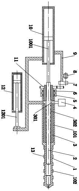
[0034] Such as Figure 1 to Figure 4 As shown, it is a coaxial injection molding machine with inner screw groove and plunger, including barrel 1, plunger 2, plasticizing screw 3, hopper 4, seat 5, radial thrust bearing group 6, transmission Mechanism 7, motor 8, injection seat frame 9, injection cylinder 10, gear 11, mobile cylinder 12 and electric heating coil 13;

[0035]The barrel 1 is divided into a plasticizing zone 101 and an injection zone 102. The diameter of the plasticizing zone 101 is larger than that of the injection zone 102. The injection zone 102 of the barrel 1 is a stepped hole type. The left section of the injection zone 102 (near the plasticizing zone) Area 101) has a large aperture, and the right section of the injection area 102 (near the injection head) has a small aperture, and a material inlet is provided at the left end of the barrel 1; the hopper 4 is installed on the barrel 1, and the outlet of the hopper 4 It communicates with the material feed por...

Embodiment 2

[0041] It is a coaxial injection molding machine with an internal screw groove and a plunger. Its working principle is basically the same as that of Embodiment 1, and its structural diagram is also the same as that of Embodiment 1. figure 1 Similar, the difference is that the injection section 102 of the barrel 1 is a through-hole type, and the structural diagram of the barrel 1 is as follows Figure 5 There is a gap between the outer circle of the plunger 2 and the inner hole of the injection section 102 of the barrel 1 to allow the melt to pass through, and the plunger 2 has been plasticized at any axial position of the injection section 102 of the barrel 1 The molten material can enter the front injection nozzle through the gap under the applied pressure.

Embodiment 3

[0043] Such as Figure 6 to Figure 10 As shown, it is a coaxial injection molding machine with an inner screw groove and a plunger, its structure and working principle are basically the same as those in Embodiment 1, the difference is the diameters of the plasticizing zone 101 and the injection zone 102 Similarly, a one-way valve 15 is installed on the right end of the plunger 2 to prevent backflow of the injection, and the one-way valve 15 is located in the injection area 102 and can move axially.

[0044] When working, the plasticizing screw 3 rotates, and the material in the hopper 4 enters the inner screw groove 302 of the plasticizing screw 3 through the material inlet of the barrel 1 and the radial channel 301 of the plasticizing screw 3, and the material is plasticized The inner screw groove 302 of the screw 3 pushes and moves forward, and then the molten material directly fills the right end of the injection area 102 of the barrel 1 through the one-way valve 15, and th...


PUM


Abstract

The invention relates to an injection molding machine with an inner threaded groove threaded rod and a plunger coaxial.The injection molding machine comprises a machine barrel, the plunger, the plastifying threaded rod, a hopper, a base, a radial thrust bearing set, a transmission mechanism, a motor, an injection base frame, an injection oil cylinder, a gear, a moving oil cylinder and an electric heating ring.The injection molding machine is characterized in that a radial channel is formed in the plastified threaded rod, and a continuous inner threaded groove through the total length is formed in the inner wall of a center hole of the plastifying threaded rod; a plastifying region and an injection region are arranged in the machine barrel, the plastifying region is located on the left part of the machine barrel, the injection region is located on the right part of the machine barrel, the plastifying threaded rod is located in the plastifying region and can rotate, when the plastifying threaded rod does rotational motion, material plastifying is completed through relative rotation between the inner threaded groove and the plunger, and the plunger moves linearly in the center hole of the injection region of the machine barrel to complete injection of the molten material.The injection molding machine has the advantages of being better in plastifying performance, simple and compact in structure and low in manufacturing, using and maintaining cost, and products are high in quality.

Description

technical field [0001] The invention relates to a coaxial injection molding machine with an internal screw groove and a plunger, which is mainly used for plasticizing and injection molding polymer materials and inorganic materials, and belongs to the technical field of material molding equipment. Background technique [0002] Injection molding is one of the main methods of plastic molding processing, and plastic injection products account for more than 30% of the total plastic products. Almost most plastics can be injection molded. [0003] The function of the injection system of the injection molding machine is to melt the polymer pellets or powder in the barrel after plasticization, and then inject the melt into the mold cavity under pressure, and provide maintaining pressure in the subsequent pressure-holding stage to make the polymerization The material continues to enter the mold cavity to fill the shrinkage caused by cooling; the performance of the plasticizing inject...

Claims


Application Information

Patent Timeline
Patent Type & Authority Patents(China)
IPC IPC(8): B29C45/54B29C45/60B29C45/62B29C45/58
CPCB29C45/541B29C45/586B29C45/60B29C45/62
Inventor 陈学锋凃明霞徐言生胡建国柯美元曾宪荣
Owner ANHUI HUATENG AGRI TECH CO LTD
Learn More