
Damping resistor

A damping resistance and resistance technology, applied in the direction of resistors, resistance terminals/electrodes, non-adjustable metal resistors, etc., can solve the problems of enlarged structure, insignificant effect, increased processing and manufacturing costs, etc., to prevent resonance and reduce interference Intensity, attenuating the effect of high frequency oscillations

Inactive Publication Date: 2016-06-01
XINGHUA YALAN MACHINERY MFG
View PDF7 Cites 0 Cited by
  • Summary
  • Abstract
  • Description
  • Claims
  • Application Information

AI Technical Summary

Problems solved by technology

However, in the high-frequency electric oscillation, the magnetoelectric mutual transformation is very fast, and the energy cannot be completely returned to the original oscillation circuit, so the electric energy and magnetic energy propagate to the space in the form of electromagnetic waves with the periodic changes of the electric field and magnetic field.
[0003] With the development of automotive electronic devices, there will be more and more electrical assemblies in the car that are susceptible to electromagnetic interference. Devices, etc. These devices themselves rely on the antenna to add a choke coil, add a filter to the power supply, choose a reasonable installation location and cover it with a metal cover to prevent electromagnetic interference, but such measures are often not effective, and, Larger structure, increased processing and manufacturing costs
[0004] Another measure to prevent electromagnetic wave interference is to take anti-interference measures for electrical assemblies that are susceptible to interference, and use damping resistors to prevent the circuit from forming equal-amplitude oscillations. Compared with the previous method, this method has improved effects. But the structure is still complicated, and the work is not stable, good and bad

Method used


Image

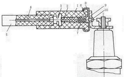
  • Damping resistor

Examples


Embodiment 1

[0019] Before installing the high-voltage line, the resistor needs to be pre-oxidized. The steps of the treatment are:

[0020] (1) The wire core 4 made of nickel-chromium-lead alloy material is mechanically polished to remove the oxide film naturally formed on the surface of the nickel-chromium-lead alloy material;

[0021] (2): Put the nickel-chromium-lead alloy into the polishing solution at a temperature of 50°C for 1 minute, and the polishing solution is composed of H with a relative density of 1.7 3 PO 4 solution and H with a relative density of 1.85 2 SO 4 The solution is configured with a volume ratio of 1:1;

[0022] (3): Place the polished nickel-chromium-lead alloy in dry air and heat it to 100°C, keep it warm for 5 hours, and then cool it in the furnace;

[0023] The left end of the wire core 4 after pre-oxidation treatment is fastened with the screw 3. The outer surface of the wire core 4 is covered with a layer of high-voltage wire 5, and the outer side of th...

Embodiment 2

[0025] Before installing the wire, the resistor needs to be pre-oxidized. The steps are:

[0026] (1) The wire core 4 made of nickel-chromium-lead alloy material is mechanically polished to remove the oxide film naturally formed on the surface of the nickel-chromium-lead alloy material;

[0027] (2): Put the nickel-chromium-lead alloy into the polishing solution with a temperature of 60°C for 1.5 minutes. The polishing solution is composed of H with a relative density of 1.7 3 PO 4 solution and H with a relative density of 1.85 2 SO 4 The solution is configured with a volume ratio of 1:1.1;

[0028] (3): Place the polished nickel-chromium-lead alloy in dry air and heat it to 150°C, keep it warm for 8 hours, and then cool it in the furnace;

[0029] The left end of the wire core 4 after pre-oxidation treatment is fastened with the screw 3. The outer surface of the wire core 4 is covered with a layer of high-voltage wire 5, and the outer side of the screw 3 is covered with a...

Embodiment 3

[0031] Before installing the wire, the resistor needs to be pre-oxidized. The steps are:

[0032] (1) The wire core 4 made of nickel-chromium-lead alloy material is mechanically polished to remove the oxide film naturally formed on the surface of the nickel-chromium-lead alloy material;

[0033] (2): Put the nickel-chromium-lead alloy into the polishing solution with a temperature of 80°C for 2 minutes. The polishing solution is composed of H with a relative density of 1.7 3 PO 4 solution and H with a relative density of 1.85 2 SO 4 The solution is configured with a volume ratio of 1:1.2;

[0034] (3): Place the polished nickel-chromium-lead alloy in dry air and heat it to 200°C, keep it warm for 10 hours, and then cool it in the furnace;

[0035] The left end of the wire core 4 after pre-oxidation treatment is fastened with the screw 3. The outer surface of the wire core 4 is covered with a layer of high-voltage wire 5, and the outer side of the screw 3 is covered with a ...


PUM


Abstract

The invention proposes a damping resistor. The damping resistor comprises a Bakelite shell, a resistor, a bolt, a cable core, a high-voltage line, a hole, a spring, a cover cup, a fastening corner bracket and a fastening element, wherein the bolt is arranged in the Bakelite shell, the hole is formed on the left side of the bolt, the resistor and the spring are arranged in the hole, the resistor is a carbon resistor, the cable core is arranged on the right side of the bolt, the outer surface of the cable core is coated with the high-voltage line, the cover cup is fixedly arranged on the left side of the Bakelite shell, and the fastening element passes through the fastening corner bracket to make the cover cup fixed on the fastening corner bracket. In the damping resistor, the damping resistor is connected in series in a high-voltage circuit of an ignition system to reduce high-frequency oscillation generated by electric spark, and thus, the interference intensity of electromagnetic wave is reduced; and since the damping resistor is arranged on a high-voltage wire lead-out end of an ignition coil, is formed by burning a nickel chrome lead alloy filament and is equivalent to a combination of an inductor, a capacitor and a resistor, the effect of suppressing the electromagnetic wave is ideal.

Description

technical field [0001] The invention relates to a resistor, in particular to a damping resistor used in a high-voltage circuit of an ignition system. Background technique [0002] Electromagnetic wave is a form of motion of electromagnetic field. In the case of high-frequency electromagnetic oscillation, part of the energy is radiated from space, and the general term for the electric wave and magnetic wave formed is called "electromagnetic wave". In the low-frequency electrical oscillation, the mutual change between magnetoelectricity is relatively slow, and almost all the energy returns to the original circuit without energy radiation. However, in the high-frequency electric oscillation, the magnetoelectric mutual transformation is very fast, and it is impossible for all the energy to return to the original oscillation circuit, so the electric energy and magnetic energy propagate to the space in the form of electromagnetic waves with the periodic changes of the electric fi...

Claims


Application Information

Patent Timeline
Patent Type & Authority Applications(China)
IPC IPC(8): H01C3/00H01C1/14H01C1/02
Inventor 张雅岚
Owner XINGHUA YALAN MACHINERY MFG
Learn More