Circulating sand dust blowing device
A technology of soot blowing device and sand, which is applied to the treatment of combustion products, combustion methods, and removal of solid residues, etc. It can solve problems affecting the health of workers, damage to the seal of boiler furnace walls, and influence on boiler operation, etc., to achieve soot blowing Good effect, high safety in use, and effect of improving safety in use
- Summary
- Abstract
- Description
- Claims
- Application Information
AI Technical Summary
Problems solved by technology
Method used
Image

Examples
Embodiment 1
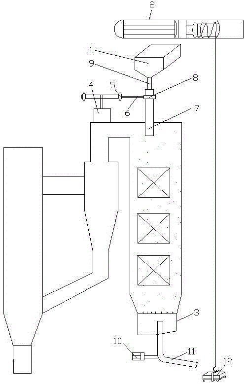
[0064] see figure 1 , a circulating sand soot blowing device, including a sand bucket 1 and an electric hoist 2 connected to the furnace roof, and also includes a sand blaster connected to the top of the tail shaft and a fluidized bed 3 connected to the bottom of the tail shaft. The sander comprises a speed regulating motor 4, a pulley 5, a transmission belt 6, a sandblasting pipe 7 and a bearing 8 connected to the sandblasting pipe 7, the sand bucket 1 is connected with the sandblasting pipe 7 through a sand feeding pipe 9, and the speed regulating motor 4 The motor shaft of the motor is connected to the pulley 5, the pulley 5 is connected to the bearing 8 through the transmission belt 6, the sandblasting pipe 7 is connected to the tail shaft, and the auger driven by the motor 10 is connected to the fluidized bed 3 11. The electric hoist 2 is connected with a sand discharge trolley 12 .
[0065] This embodiment is the most basic implementation mode. The sand blaster includes...
Embodiment 2
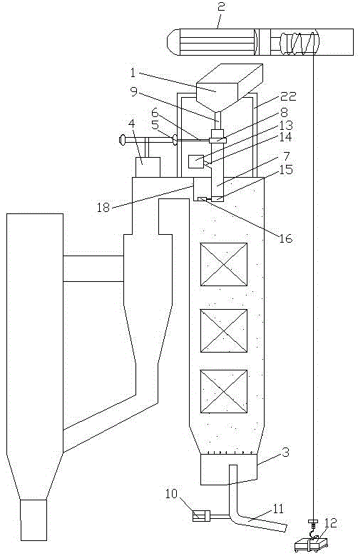
[0067] see figure 2 and image 3 , a circulating sand soot blowing device, including a sand bucket 1 and an electric hoist 2 connected to the furnace roof, and also includes a sand blaster connected to the top of the tail shaft and a fluidized bed 3 connected to the bottom of the tail shaft. The sander comprises a speed regulating motor 4, a pulley 5, a transmission belt 6, a sandblasting pipe 7 and a bearing 8 connected to the sandblasting pipe 7, the sand bucket 1 is connected with the sandblasting pipe 7 through a sand feeding pipe 9, and the speed regulating motor 4 The motor shaft of the motor is connected to the pulley 5, the pulley 5 is connected to the bearing 8 through the transmission belt 6, the sandblasting pipe 7 is connected to the tail shaft, and the auger driven by the motor 10 is connected to the fluidized bed 3 11. The electric hoist 2 is connected with a sand discharge trolley 12 .
[0068]An induced draft fan 13 is connected on the top of the tail shaft,...
Embodiment 3
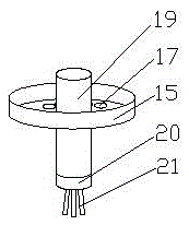
[0076] see Figure 3-Figure 5 , a circulating sand soot blowing device, including a sand bucket 1 and an electric hoist 2 connected to the furnace roof, and also includes a sand blaster connected to the top of the tail shaft and a fluidized bed 3 connected to the bottom of the tail shaft. The sander comprises a speed regulating motor 4, a pulley 5, a transmission belt 6, a sandblasting pipe 7 and a bearing 8 connected to the sandblasting pipe 7, the sand bucket 1 is connected with the sandblasting pipe 7 through a sand feeding pipe 9, and the speed regulating motor 4 The motor shaft of the motor is connected to the pulley 5, the pulley 5 is connected to the bearing 8 through the transmission belt 6, the sandblasting pipe 7 is connected to the tail shaft, and the auger driven by the motor 10 is connected to the fluidized bed 3 11. The electric hoist 2 is connected with a sand discharge trolley 12 .
[0077] An induced draft fan 13 is connected on the top of the tail shaft, and...
PUM
 Abstract
Description
Claims
Application Information
 - R&D
- Intellectual Property
- Life Sciences
- Materials
- Tech Scout
- Unparalleled Data Quality
- Higher Quality Content
- 60% Fewer Hallucinations
Browse by: Latest US Patents, China's latest patents, Technical Efficacy Thesaurus, Application Domain, Technology Topic, Popular Technical Reports.
© 2025 PatSnap. All rights reserved.Legal|Privacy policy|Modern Slavery Act Transparency Statement|Sitemap|About US| Contact US: help@patsnap.com