A steel box-concrete composite main girder and construction method for long-span cable-stayed bridges

Active Publication Date: 2017-03-29
TSINGHUA UNIV
View PDF8 Cites 0 Cited by
  • Summary
  • Abstract
  • Description
  • Claims
  • Application Information

AI Technical Summary

Problems solved by technology

Due to the shear lag effect in the force transmission of the cables, the steel box close to the longitudinal axis of the cable stays bears huge pressure. The traditional design mainly uses thick steel plates, longitudinal stiffeners, and diaphragms to meet the axial pressure and the stability of the steel plates. problems, but there are problems such as complex structure, heavy welding workload, and large steel consumption

Method used


Image

  • A steel box-concrete composite main girder and construction method for long-span cable-stayed bridges
  • A steel box-concrete composite main girder and construction method for long-span cable-stayed bridges
  • A steel box-concrete composite main girder and construction method for long-span cable-stayed bridges

Examples


Embodiment 1

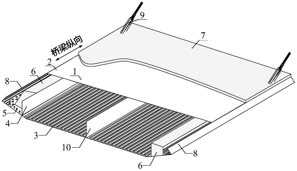
[0033] Steel box-concrete composite girder for long-span cable-stayed bridges, the composite girder includes single-box multi-chamber streamlined flat steel box girder 1, side web 4, such as figure 1 , 2 As shown, the single-box multi-room streamlined flat steel box girder includes steel roof 2, steel bottom plate 3, bridge deck system 7, air nozzle 8, and middle web 10, and the side webs are welded on both sides of the single-box multi-room streamlined flat steel box girder The plate 4 forms a box chamber, and the shear connector 5 is welded on the inside of the box chamber, and the concrete 6 is poured to form a whole, which jointly bears the coupling effect of the compression and bending load, and avoids the buckling of the steel plate.

Embodiment 2

[0035] Steel box-concrete composite girder for long-span cable-stayed bridges, the composite girder includes split double-box steel box girder 11, side web 4, such as image 3 , 4 As shown, the split-type double-box steel box girder includes steel roof 2, steel bottom plate 3, bridge deck system 7, air nozzle 8, and transverse connector 12, which are formed by welding side webs 4 on both sides of the split-type double-box steel box girder. The box chamber is formed by welding shear connectors 5 and pouring concrete 6 on the inside of the box chamber to jointly undertake the coupling effect of compression and bending loads and avoid buckling of the steel plate. The transverse connecting member 12 may be an I-beam, a diaphragm or a diagonal bar type transverse connecting system.

[0036] The deck system described in the above embodiments is an orthotropic steel deck pavement system or a steel-concrete composite deck system.

[0037] In the above embodiment, the height of concr...


PUM


Abstract

The invention relates to a steel box-concrete composite girder for a long-span cable-stayed bridge and a construction method, belonging to the technical field of bridge engineering. The steel box-concrete composite girder comprises a single-box multi-chamber streamlined flat steel box beam and is characterized by also comprising side webs and shear connectors, wherein the side webs are positioned at the two sides of the single-box multi-chamber streamlined flat steel box beam so as to encircle a closed chamber; and the shear connectors are welded at the inner side of the chamber, and concrete is poured. The concrete in the steel box beam provided by the invention has large axial rigidity and high carrying capacity, can bear the huge axial force and bending moment in a longitudinal bridge direction, obviously reduces the thickness of steel plates of the steel box beam, the quantity of stiffening ribs, transverse diaphragms and welded seams, the steel consumption and the like, reduces the cross section height, and has obvious economic benefits.

Description

technical field [0001] The invention relates to a steel box-concrete composite main girder for a long-span cable-stayed bridge and a construction method, belonging to the technical field of bridge engineering. Background technique [0002] At present, the main girder system of long-span cable-stayed bridges mostly uses steel box girders. Steel box girders can be divided into flat streamlined single box multi-chamber steel box girders and split double box girders. Calculation analysis and engineering practice show that since the cable-stayed cables are self-anchored on the main girder, the horizontal component force of the cable-stayed tension is transformed into the axial pressure of the main girder, and the axial pressure increases with the increase of the span of the cable-stayed bridge , especially near the bridge tower. Due to the shear lag effect in the force transmission of the cables, the steel box close to the longitudinal axis of the cable stays bears huge pressur...

Claims


Application Information

Patent Timeline
Patent Type & Authority Patents(China)
IPC IPC(8): E01D11/04E01D2/04E01D19/00
CPCE01D2/04E01D11/04E01D19/00E01D2101/268
Inventor 聂建国汪家继
Owner TSINGHUA UNIV
Why Eureka
Try Eureka