
Coiling block stall braking system and hoisting device

A braking system and reel technology, applied in hoisting devices, spring mechanisms, etc., can solve the problems of electrical system failure, electrical system failure, detection speed or motion state consumption, failure, etc.

Active Publication Date: 2016-04-13
ZOOMLION HEAVY IND CO LTD
View PDF5 Cites 6 Cited by
  • Summary
  • Abstract
  • Description
  • Claims
  • Application Information

AI Technical Summary

Problems solved by technology

[0006] In the above-mentioned prior art, it is necessary to prevent the crane from stalling through electrical links, but the electrical system is prone to failure due to electromagnetic interference, contact ablation and other reasons; it takes a certain amount of time to detect the speed or motion state, especially the hydraulic safety. After the tongs received the control command, it took a certain amount of time to start the pumping station to drive the oil cylinder, and factors such as oil compressibility lead to slow braking response of the hydraulic safety tongs, and braking through the hydraulic safety tongs is easily affected by the clamping force and clamping force of the hydraulic safety tongs. Influenced by the two factors of the friction coefficient of the holding surface, insufficient clamping force or friction coefficient may cause the initial failure of the stall brake, and when the crane stalls to a certain extent, the structural vibration will intensify, and the hydraulic safety gear is difficult to clamp stably. Holding force may also lead to serious consequences of wire rope breakage
[0007] In summary, the braking methods for crane stalls in the prior art mainly have the following defects: poor reliability, slow response, and poor stability

Method used


Image

  • Coiling block stall braking system and hoisting device
  • Coiling block stall braking system and hoisting device
  • Coiling block stall braking system and hoisting device

Examples


Embodiment Construction

[0046]Specific embodiments of the present invention will be described in detail below in conjunction with the accompanying drawings. It should be understood that the specific embodiments described here are only used to illustrate and explain the present invention, and are not intended to limit the present invention.

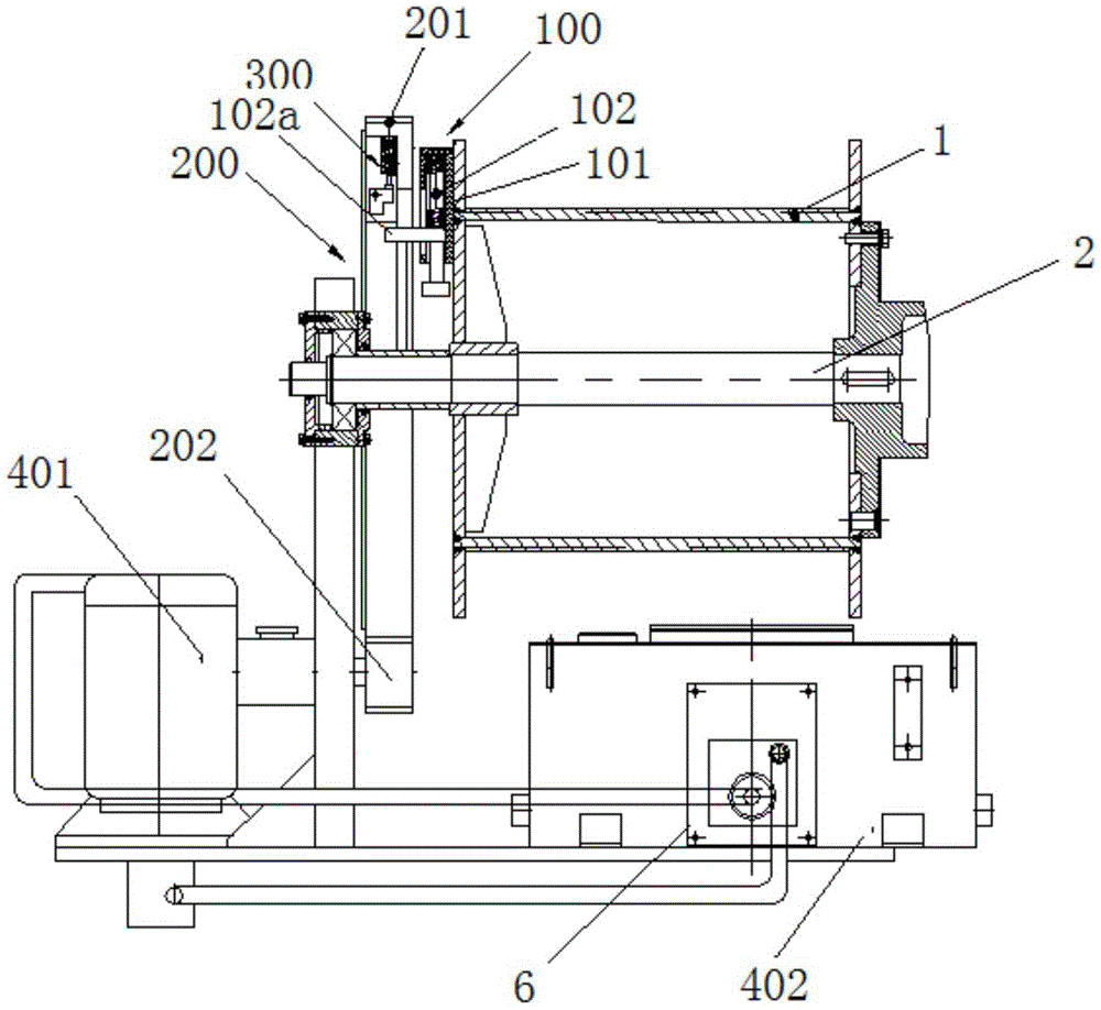
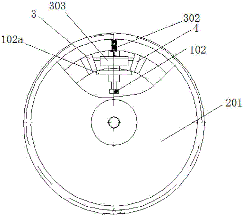
[0047] see figure 1 , according to one aspect of the present invention, a drum stall braking system is provided, wherein the drum stall braking system includes: a centrifugal trigger mechanism 100, the centrifugal trigger mechanism 100 includes a first axial end fixed to the drum 1 A fixed portion 101 and a first sliding portion 102 slidably connected to the first fixed portion 101, a transmission mechanism 200, the transmission mechanism 200 includes a first transmission wheel 201 spaced apart from the axial end surface of the reel 1, the first transmission The wheel 201 is set coaxially with the reel 1, and the first transmission wheel 201 is equipped with an ...


PUM


Abstract

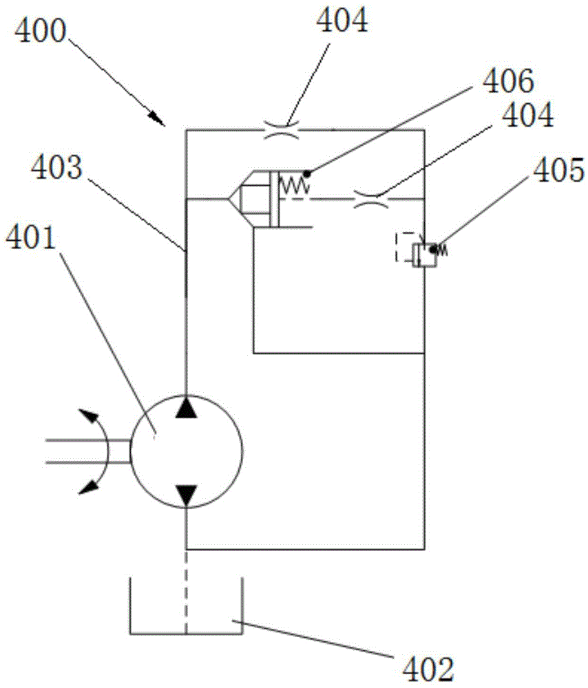
The invention discloses a coiling block stall braking system and a hoisting device. The coiling block stall braking system comprises a centrifugal triggering mechanism (100), a transmission mechanism (200) and a hydraulic buffering system (400). The centrifugal triggering mechanism (100) comprises a first fixed part (101) fixed to the axial end of a coiling block (1), and a first sliding part (102) connected to the first fixed part (101) in a sliding manner. The transmission mechanism (200) comprises a first transmission wheel (201) spaced from the axial end face of the coiling block (1). The first transmission wheel (201) and the coiling block (1) are coaxially arranged, and the first transmission wheel (201) is provided with a connecting part (300) used for being connected with or separated from the first sliding part (102). A hydraulic pump (401) is arranged in the hydraulic buffering system (400) and is in transmission connection with the first transmission wheel (201). The coiling block stall braking system is high in reliability, fast in response and high in stability.

Description

technical field [0001] The invention relates to braking equipment, in particular to a drum stall braking system and lifting equipment. Background technique [0002] Crane stall refers to the phenomenon that during the hoisting work of the crane, due to electrical and mechanical failures or operational errors, the reel speed of the crane is too high, resulting in heavy objects not rising but falling and stalling and falling. Therefore, once the crane stalls, the fall of its hoisted heavy objects can easily cause safety accidents, resulting in casualties or heavy property losses. [0003] The braking methods for crane stall in the prior art mainly include: [0004] 1. Install protective devices on the electrical system of the crane to improve the reliability of the electrical system. For example, install a speed measuring device on the tail of the drive motor of the crane drum or on the transmission shaft between the motor and the reducer, and make the speed measurement The ...

Claims


Application Information

Patent Timeline
IPC IPC(8): B66D1/54B66D5/02B66D5/04
CPCB66D1/54B66D5/026B66D5/04B66D2700/03
Inventor 赵业亮刘洋
Owner ZOOMLION HEAVY IND CO LTD
Learn More