Deep coupling utilization system for turbine steam exhaust waste heat and boiler flue gas waste heat

A technology of boiler flue gas and steam turbine, which is applied in the field of deep utilization system of steam turbine waste steam waste heat coupled with boiler flue gas waste heat, which can solve the problems of low grade of waste heat utilization energy, limited unit efficiency space, increased fan power consumption, etc., to achieve reduction Effects of energy consumption, reduction of heat dissipation loss and evaporation loss, and increase of flue gas temperature

Inactive Publication Date: 2016-03-16
中国大唐集团科学技术研究总院有限公司
View PDF6 Cites 2 Cited by
  • Summary
  • Abstract
  • Description
  • Claims
  • Application Information

AI Technical Summary

Problems solved by technology

However, due to the current technical measures such as low-temperature economizer, due to the influence of low-temperature corrosion and other factors on the exhaust gas temperature, the energy grade of waste heat utilization is low, and the space for improving unit efficiency is limited.
In addition, the air preheater of the important auxiliary equipment of the boiler has the problems of low-temperature corrosion that leads to large air leakage and increased power consumption of the fan. At the same time, after the SCR flue gas denitrification device is put into operation, the low flue gas temperature also leads to ammonia bisulfate generated after the ammonia escapes. It is easy to accumulate on the heating surface of the air preheater to cause corrosion and blockage

Method used


Image

  • Deep coupling utilization system for turbine steam exhaust waste heat and boiler flue gas waste heat

Examples


Embodiment Construction

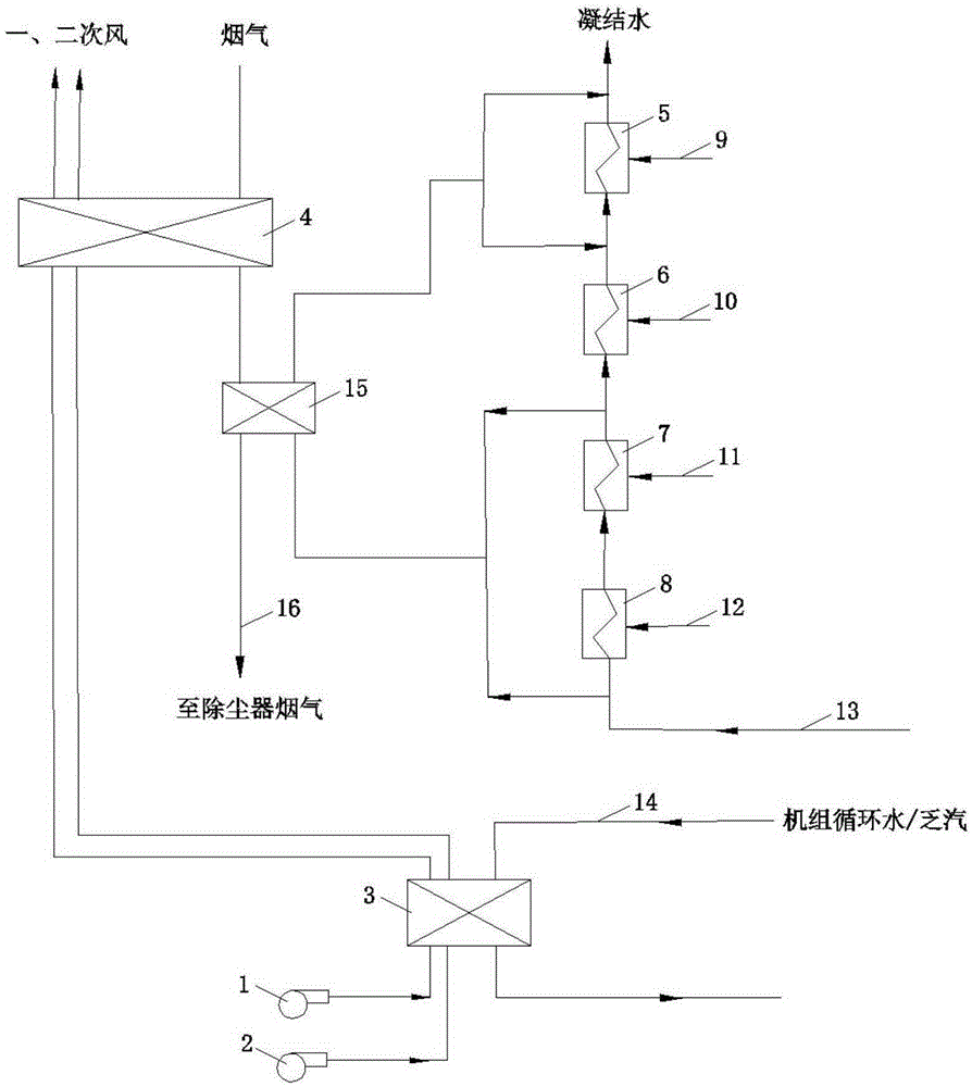
[0015] Such as figure 1 As shown, the steam turbine exhaust steam waste heat coupling boiler flue gas waste heat depth utilization system of the present invention includes a primary fan 1 and a secondary fan 2, and the air inlet of the primary fan 1 and the air inlet of the secondary fan 2 are respectively connected to the outside atmosphere. The air outlet of fan 1 is connected to the air inlet of the primary air delivery pipeline, the middle part of the primary air delivery pipeline passes through the primary air heat exchange channel of the air preheater 4, the air outlet of the secondary fan 2 is connected to the secondary air The air inlets of the conveying pipelines are connected, the middle part of the secondary air conveying pipeline passes through the secondary air heat exchange channel of the air preheater 4, and a flue gas channel is provided on one side of the air preheater 4, and the air preheater 4 The flue gas channel is connected in series in the middle of the ...


PUM


Abstract

The invention aims to provide a deep coupling utilization system for turbine steam exhaust waste heat and boiler flue gas waste heat in order to improve the heat efficiency of a generator set, lower the energy consumption and reduce the pollution. The deep coupling utilization system for the turbine steam exhaust waste heat and the boiler flue gas waste heat comprises a primary fan and a secondary fan. An exhaust port of the primary fan is connected to an air inlet of a primary air conveying pipeline, and the middle of the primary air conveying pipeline penetrates through a primary air heat exchange channel of an air pre-heater. An exhaust port of the secondary fan is connected to an air inlet of a secondary air conveying pipeline, and the middle of the secondary air conveying pipeline penetrates through a secondary air heat exchange channel of the air pre-heater. A flue gas channel is formed in one side of the air pre-heater and is connected to the middle of a flue in series, and a dust remover is arranged at the outlet end of the flue. An air heater is connected to the parts, located at the air inlet section of the air pre-heater, of the primary air conveying pipeline and the secondary air conveying pipeline in series.

Description

technical field [0001] The invention relates to a deep utilization system for waste heat of exhaust steam of a steam turbine coupled with waste heat of boiler flue gas. Background technique [0002] Currently, thermal power units still play an important role in the electricity production of major economies. With the decrease of fossil energy, the increasing requirements of environmental protection and the national energy industry policy put forward higher standards for energy saving and consumption reduction of thermal power generation, how to further reduce the energy consumption per unit of power generation to achieve energy saving and emission reduction is an important task for power generation enterprises. [0003] Based on the steam Rankine power cycle theory, when the unit generates electricity, the exhaust steam of the steam turbine needs to produce a large amount of energy loss, which accounts for about 40% of the input energy of the unit. The technical measures for...

Claims


Application Information

Patent Timeline
IPC IPC(8): F23L15/00F23J15/06
CPCF23J15/06F23L15/00F23L2900/15043F23L2900/15044Y02E20/34
Inventor 张振华孙英博万逵芳赵文波刘彦鹏邢洪涛曹涛郭婷婷张志刚
Owner 中国大唐集团科学技术研究总院有限公司
Why Eureka
Try Eureka