
Reduction smelting regenerative combustion system and method for smelting using the system

A combustion system and regenerative technology, applied in the field of smelting, can solve the problems of unreasonable burner position, oxidative burning of materials, and increase the difficulty of on-site construction, so as to improve the efficiency of waste heat recovery, the speed of heat storage and heat release, The effect of improving energy efficiency

Active Publication Date: 2019-03-29
SHENWU TECH GRP CO LTD
View PDF12 Cites 0 Cited by
  • Summary
  • Abstract
  • Description
  • Claims
  • Application Information

AI Technical Summary

Problems solved by technology

However, when the existing regenerative burner is applied to the melting furnace, because the heat load required by the smelting process is much higher than that of the metallurgical heating furnace, the amount of flue gas produced is large, the volume of the regenerator is relatively large, and The position of the burner on the furnace body is unreasonable, which increases the difficulty of on-site construction, and causes inconvenience to installation, use, and maintenance. At the same time, the dust generated by this type of regenerative burner during the smelting process is likely to cause blockage of the regenerative body. The high frequency of regenerator replacement increases the operating cost of this type of burner. In addition, this type of regenerative burner does not consider the combustion effect. Insufficient mixing, low combustion efficiency, local temperature and excessively high nitrogen oxides, etc., cause oxidation and burning of materials during the smelting process

Method used


Image

  • Reduction smelting regenerative combustion system and method for smelting using the system
  • Reduction smelting regenerative combustion system and method for smelting using the system
  • Reduction smelting regenerative combustion system and method for smelting using the system

Examples


Embodiment Construction

[0048] Embodiments of the present invention are described in detail below, examples of which are shown in the drawings, wherein the same or similar reference numerals designate the same or similar elements or elements having the same or similar functions throughout. The embodiments described below by referring to the figures are exemplary and are intended to explain the present invention and should not be construed as limiting the present invention.

[0049] In describing the present invention, it should be understood that the terms "center", "longitudinal", "transverse", "length", "width", "thickness", "upper", "lower", "front", " Back", "Left", "Right", "Vertical", "Horizontal", "Top", "Bottom", "Inner", "Outer", "Clockwise", "Counterclockwise", "Axial" , "radial", "circumferential" and other indicated orientations or positional relationships are based on the orientations or positional relationships shown in the drawings, which are only for the convenience of describing the ...


PUM


Abstract

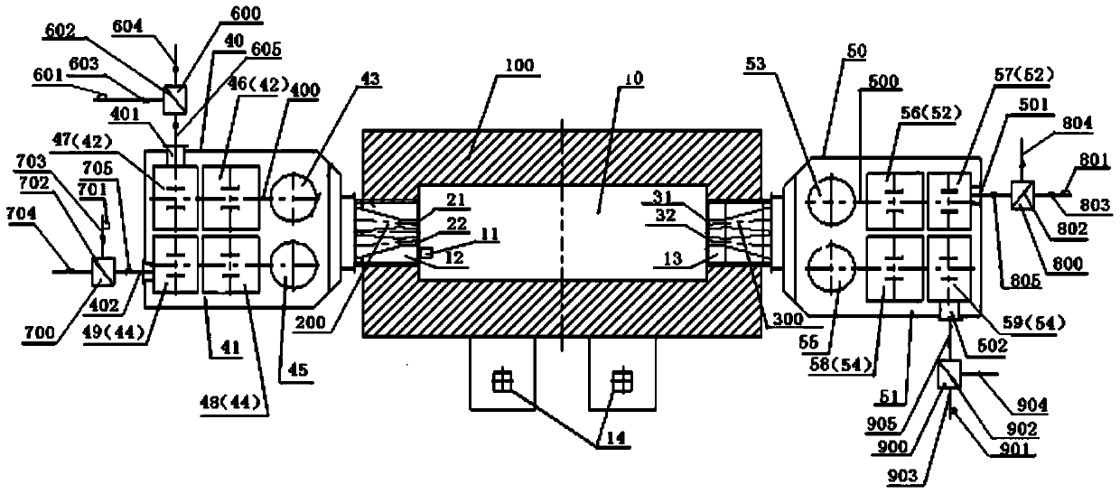
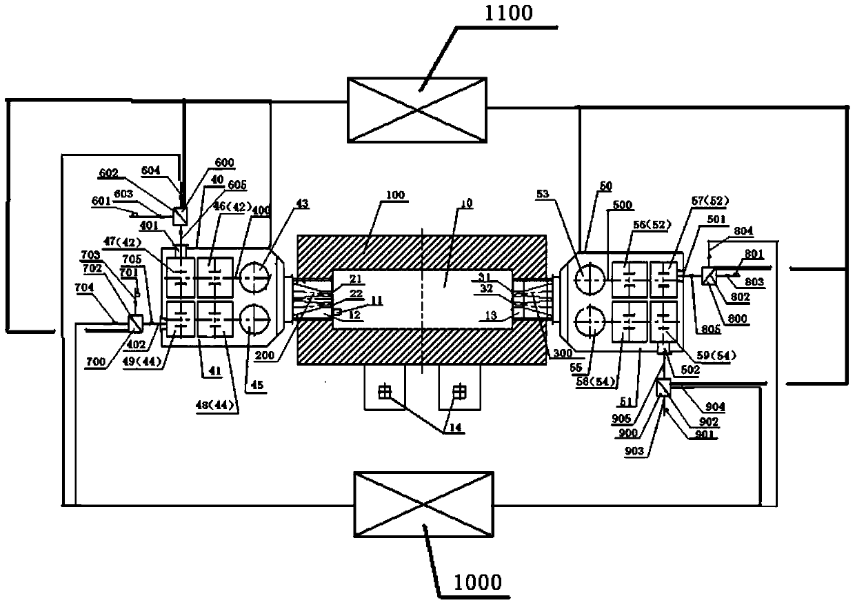
The invention discloses a reductive smelting heat-accumulation type combustion system and a smelting method using the same. The reductive smelting heat-accumulation type combustion system comprises a furnace body, a first nozzle, a second nozzle, a first heat accumulation device, a second heat accumulation device, a first air three-way valve, a first coal gas three-way valve, a second air three-way valve and a second coal gas three-way valve. The first heat accumulation device comprises a first shell. A first heat storage space is defined in the first shell. A first air heat accumulator, a first settling chamber, a first coal gas heat accumulator and a second settling chamber are arranged in the first heat storage space. The second heat accumulation device comprises a second shell. A second heat storage space is defined in the second shell. A second heat accumulator, a third settling chamber, a second coal gas heat accumulator and a fourth settling chamber are arranged in the second heat storage space. By the adoption of the reductive smelting heat-accumulation type combustion system, waste heat in smoke can be efficiently recovered, and thus the energy utilization rate is remarkably increased.

Description

technical field [0001] The invention belongs to the technical field of smelting, in particular, the invention relates to a reduction smelting regenerative combustion system and a method for smelting using the system. Background technique [0002] The gas-fired melting furnace improves the direct reduction-melting process of the coal-based rotary hearth furnace, and plays a vital role in the slag-iron separation process after smelting resources such as refractory ore, laterite nickel ore, vanadium-titanium magnetite, and sulfuric acid slag. , breaking the singleness of the submerged arc furnace smelting process, and can save a lot of electric energy at the same time, and also provides a feasible solution for areas with weak industrial foundations. [0003] Regenerative combustion technology is the most widely used energy-saving and environmentally friendly combustion technology in industrial furnaces at this stage, and this technology is quite mature. However, when the exist...

Claims


Application Information

Patent Timeline
Patent Type & Authority Patents(China)
IPC IPC(8): F23D14/66F27D17/00
CPCY02E20/34Y02P10/25
Inventor 石为华王东方吴道洪
Owner SHENWU TECH GRP CO LTD
Learn More