
Thermal microvalves

a micro-scale device and micro-scale technology, applied in the direction of valve details, flow mixers, chemical vapor deposition coatings, etc., can solve the problem that multi-component devices can be readily assembled and achieve the effect of easy assembly into complex, integrated systems

Inactive Publication Date: 2005-12-08
RGT UNIV OF MICHIGAN
View PDF33 Cites 68 Cited by
  • Summary
  • Abstract
  • Description
  • Claims
  • Application Information

AI Technical Summary

Benefits of technology

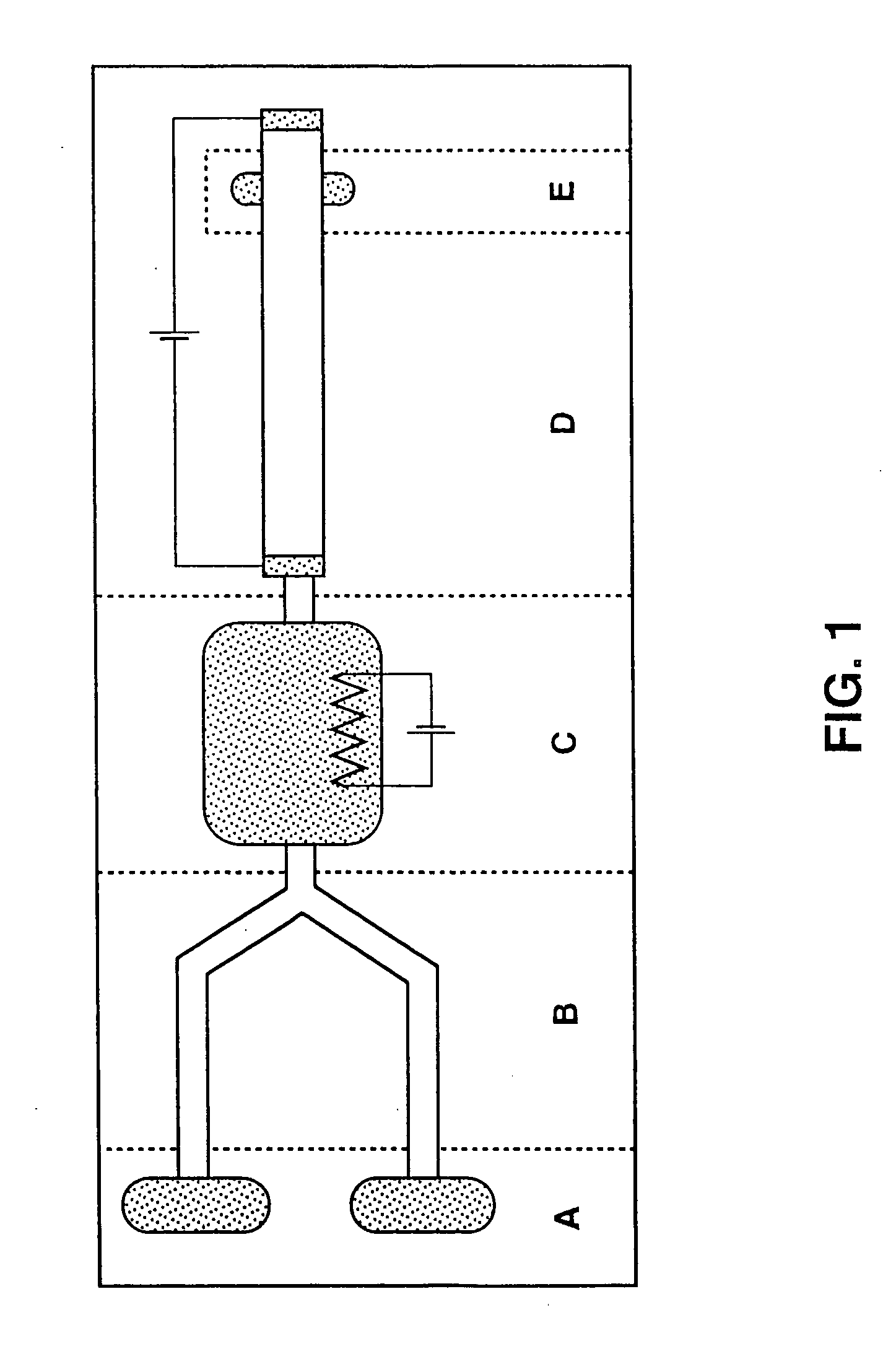
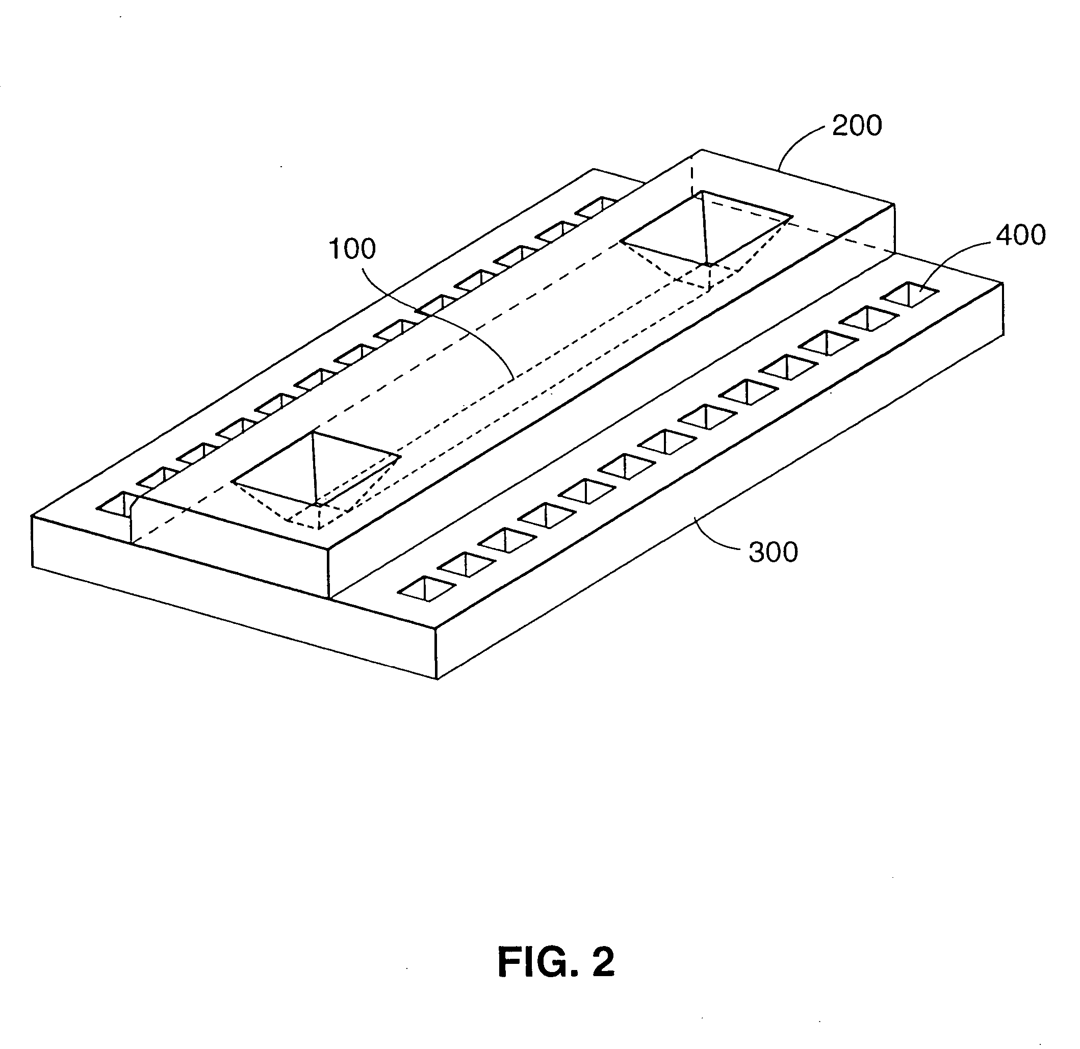
[0014] The present invention relates to microfabrication of microscale devices and reactions in microscale devices, and in particular, movement of biological samples in microdroplets through microchannels to initiate biological reactions. The present invention contemplates microscale devices, comprising microdroplet transport channels, reaction regions (e.g. chambers), electrophoresis modules, and radiation detectors. In a preferred embodiment, these elements are microfabricated from silicon and glass substrates. The various components are linked (i.e., in liquid communication) using a surface-tension-gradient mechanism in which discrete droplets are differentially heated and propelled through etched channels. Electronic components are fabricated on the same substrate material, allowing sensors and controlling circuitry to be incorporated in the same device. Since all of the components are made using conventional photolithographic techniques, multi-component devices can be readily assembled into complex, integrated systems.
[0015] It is not intended that the present invention be limited by the nature of the reactions carried out in the microscale device. Reactions include, but are not limited to, chemical and biological reactions. Biological reactions include, but are not limited to sequencing, restriction enzyme digests, RFLP, nucleic acid amplification, and gel electrophoresis. It is also not intended that the invention be limited by the particular purpose for carrying out the biological reactions. In one medical diagnostic application, it may be desirable to differentiate between a heterozygotic and homozygotic target and, in the latter case, specifying which homozygote is present. Where a given genetic locus might code for allele A or allele a, the assay allows for the differentiation of an AA from an Aa from an aa pair of alleles. In another medical diagnostic application, it may be desirable to simply detect the presence or absence of specific allelic variants of pathogens in a clinical sample. For example, different species or subspecies of bacteria may have different susceptibilities to antibiotics; rapid identification of the specific species or subspecies present aids diagnosis and allows initiation of appropriate treatment.
[0017] It has been found empirically that the methods and devices of the present invention can be used with success when, prior to the conveying described above the transport channel (or channels) is treated with a hydrophilicity-enhancing compound. It is not intended that the invention be limited by exactly when the treatment takes place. Indeed, there is some flexibility because of the long-life characteristics of some enhancing compounds.
[0020] In one embodiment, said first microdroplet comprises nucleic acid and said second microdroplet comprises a nuclease capable of acting on said nucleic acid. In this embodiment, it is desirable to enhance the mixing within the merged microdroplet. This can be achieved a number of ways. In one embodiment for mixing, after the conveying of step (d), the flow direction is reversed. It is not intended that the present invention be limited by the nature or number of reversals. If the flow direction of said merged microdroplet is reversed even a single time, this process increases the mixing of the reactants.
[0035]“Liquid barrier” or “moisture barrier” is any structure or treatment process on existing structures that prevents short circuits and / or damage to electronic elements (e.g., prevents the destruction of the aluminum heating elements). In one embodiment of the present invention, the liquid barrier comprises a first silicon oxide layer, a silicon nitride layer, and a second silicon oxide layer.
[0036]“Merging” is distinct from “mixing.” When a first and second microdroplet is merged to create a merged microdroplet, the liquid may or may not be mixed. Moreover, the degree of mixing in a merged microdroplet can be enhanced by a variety of techniques contemplated by the present invention, including by not limited to reversing the flow direction of the merged microdroplet.

Problems solved by technology

Since all of the components are made using conventional photolithographic techniques, multi-component devices can be readily assembled into complex, integrated systems.

Method used


Image

  • Thermal microvalves
  • Thermal microvalves
  • Thermal microvalves

Examples


example 1

[0105] This example describes approaches to the problem of forming a moisture barrier over electrical elements of the microscale device. Initial prototypes employed 5000 angstroms of aluminum and covered it with PECVD SiOx. Upon testing, it was determined that the liquids were penetrating this later and destroying the aluminum heating elements.

[0106] Without clear evidence what was causing this problem, it was hypothesized that the step height of the aluminum was causing cracks in the passivation layer (the oxide). In order to alleviate the cracking problem, a layer of SixNy was tried between two layers of SiOx, with the thought that the additional thickness would overcome the cracking caused by the step height. It did not.

[0107] As a follow-up approach, a thinner layer (500 angstroms) of aluminum was tried. This gave 1 / 10 th the step height of the original prototype devices. On top of this aluminum, a triple layer of SiOx, SixNy, and SiOx was employed. Moreover, the process for m...

example 2

[0109] This example describes approaches to enhancing droplet motion by surface treatment. In this regard, the principle of using surface tension to cause droplets to move may be applied to either hydrophilic or hydrophobic surfaces. Glass, for instance, is naturally hydrophilic with a near zero contact angle with water. Because the oxide coating of the present invention is made principally of the same material as glass, it was expected that the devices would also exhibit near zero angles. It was discovered, however, that the actual construction materials had contact angles far from zero, thus enhancing the effects of contact angle hysteresis (discussed in greater detail in Example 3). For instance, water gave a contact angle (static) of ˜42° on polyamide, ˜41° on SiO2 (major component of most glasses), ˜62° on silicone spray. To enhance the surface effectiveness, several treatment processes for both hydrophilic and hydrophobic surfaces were tried, as described below.

[0110] To impr...

example 3

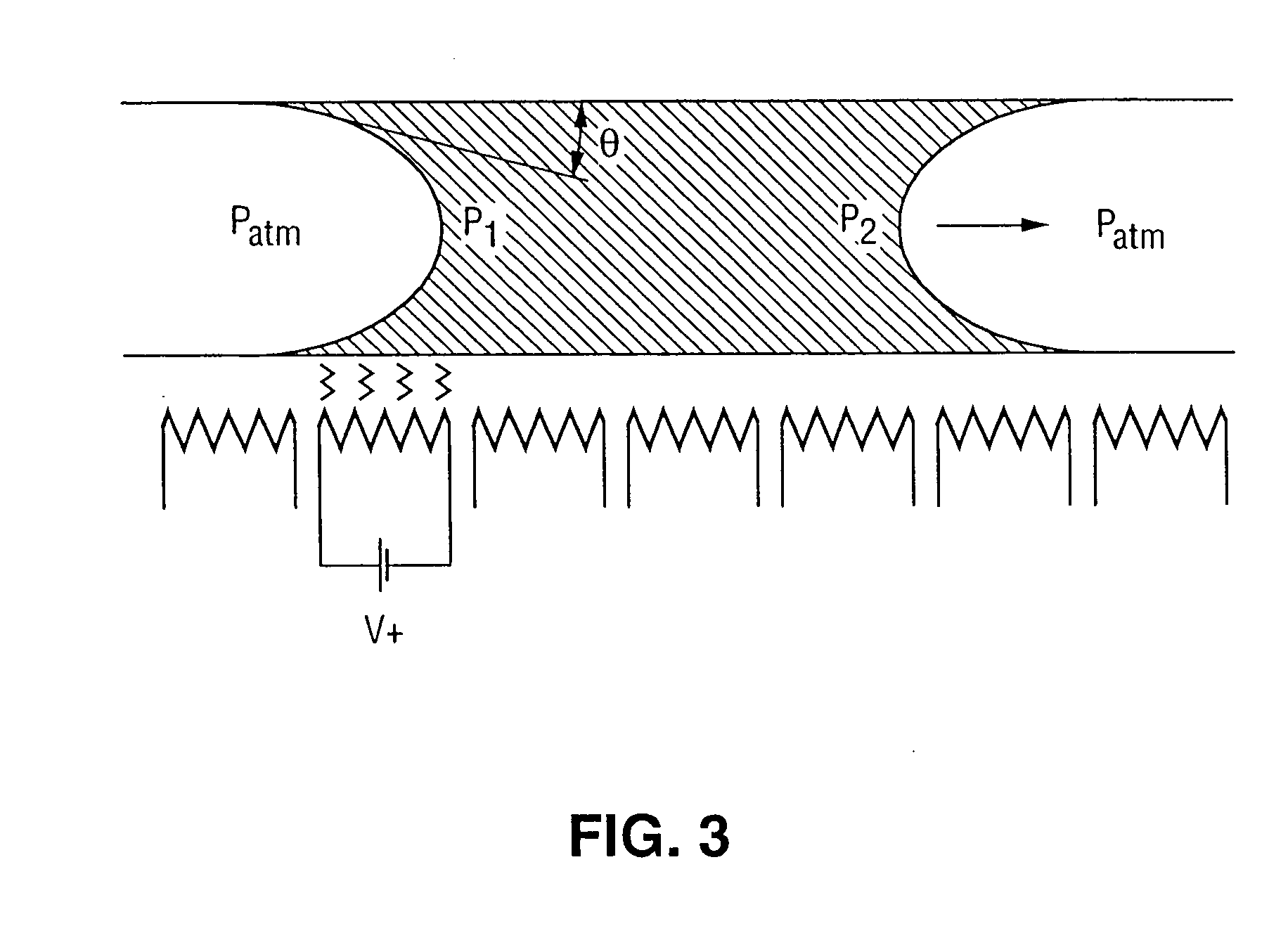
[0113] This example describes approaches to droplet motion by heat treatment. As noted previously (above), the contact angle on the advancing end of a liquid droplet in motion (known as the advancing contact angle) is greater that the that on the receding end (receding contact angle). In the case of a hydrophilic surface—such as water on glass—this tends to create a back pressure countering attempts at forward motion by heating the back side of a droplet. This is best shown by a simple model describing laminar flow through a channel.

[0114] Average Flow Through a Circular Channel:

v>=−ΔP*[R2 / (8 μL]

where: [0115]Δ=value at back−value at front end of droplet [0116]ΔP=(1 / R)*(ΔG)=pressure difference between droplet ends [0117]ΔG=change in surface tension between the ends of the droplet. [0118] R=channel radius [0119] L=droplet length [0120]μ=viscosity

Also, for water, ΔG=−constant*ΔT, where temperature increases lower the surface tension of most liquids (constant=0.16 dyn / cm for wate...


PUM

PropertyMeasurementUnit
cross-sectional areaaaaaaaaaaa
volumeaaaaaaaaaa
temperatureaaaaaaaaaa

Abstract

The movement and mixing of microdroplets through microchannels is described employing silicon-based microscale devices, comprising microdroplet transport channels, reaction regions, electrophoresis modules, and radiation detectors. The discrete droplets are differentially heated and propelled through etched channels. Electronic components are fabricated on the same substrate material, allowing sensors and controlling circuitry to be incorporated in the same device.

Description

FIELD OF THE INVENTION [0001] The present invention relates to microfabrication of microscale devices and reactions in microscale devices, and in particular, movement of biological samples in microdroplets through microchannels to initiate biological reactions. BACKGROUND [0002] The complexity and power of biological reactions has increased dramatically over the last thirty years. The initial observations of the “hybridization” process, i.e., the ability of two polymers of nucleic acid containing complementary sequences to find each other and anneal through base pairing interaction, by Marmur and Lane, Proc. Nat. Acad. Sci., U.S.A. 46, 453 (1960) and Doty et al. Proc. Nat. Acad. Sci., U.S.A. 46, 461 (1960), have been followed by the refinement of this process into an essential tool of modern biology. [0003] Initial hybridization studies, such as those performed by Hayashi et al., Proc. Nat. Acad. Sci., U.S.A. 50, 664 (1963), were formed in solution. Further development led to the im...

Claims


Application Information

Patent Timeline
Patent Type & Authority Applications(United States)
IPC IPC(8): B01F5/04B01F13/00B81B3/00B01J19/00B01L3/00B01L7/00B81C1/00C12M1/34C12Q1/68F15B13/00F15B13/08F15C5/00F16K31/02F16K31/64F16K99/00G01N37/00H01L27/14
CPCB01F5/0085B01F5/0403B01F13/0071B01F13/0072B01F13/0084B01F13/0093B01F15/0232B01J19/0093B01J2219/00783B01J2219/00822B01J2219/00828B01J2219/00831B01J2219/00837B01J2219/00853B01J2219/0086B01J2219/00873B01J2219/00889B01J2219/00891B01J2219/00957B01J2219/00961B01J2219/0097B01L3/50273B01L3/502738B01L3/502784B01L7/52B01L2200/0605B01L2300/0816B01L2300/1827B01L2400/0442B01L2400/0487B01L2400/0677B01L2400/0688B01L2400/0694B82Y30/00F15B13/0807F15C5/00F16K99/0001F16K99/0015F16K99/0017F16K99/0019F16K99/0034F16K99/0044F16K99/0061F16K2099/0071F16K2099/0074F16K2099/0076F16K2099/008F16K2099/0084Y10S366/04Y10T137/1812Y10T436/2575B01F25/14B01F25/31B01F33/3022B01F33/3021B01F33/30351B01F33/3039B01F35/7172
Inventor BURNS, MARK A.JOHNSON, BRIAN N.CHEN, MICHAEL
Owner RGT UNIV OF MICHIGAN
Learn More