
Multi-tenant-oriented cloud network architecture

A cloud network and cloud gateway technology, applied in the field of data transmission, can solve problems such as inability to serve, poor performance of a single node, DDoS attacks, etc., to achieve the effect of improving attack defense capabilities and expanding network performance

Active Publication Date: 2016-03-09
北京云启志新科技股份有限公司
View PDF4 Cites 65 Cited by
  • Summary
  • Abstract
  • Description
  • Claims
  • Application Information

AI Technical Summary

Problems solved by technology

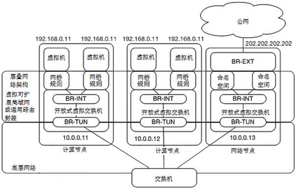
Since the NetworkNode node directly faces the public network, its single node performance is poor, and it cannot be expanded in a cluster. Therefore, for a virtual machine user, the network node corresponding to the user is easily unable to serve due to distributed denial-of-service DDoS attacks.
At present, a single NetworkNode node is easily paralyzed due to flooding attack synflood or large bandwidth attack

Method used


Image

  • Multi-tenant-oriented cloud network architecture
  • Multi-tenant-oriented cloud network architecture
  • Multi-tenant-oriented cloud network architecture

Examples


Embodiment 1

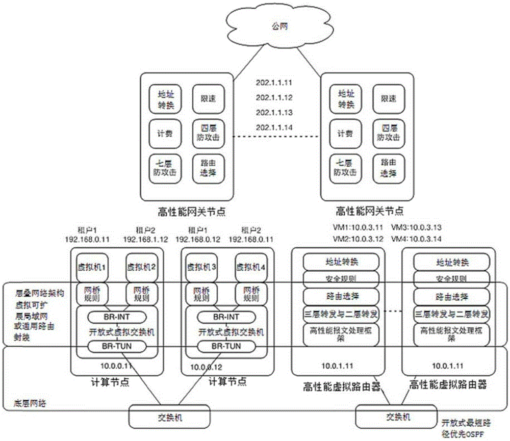
[0016] Figure 3A This is a schematic structural diagram of a multi-tenant-oriented cloud network architecture provided in the first embodiment of the present invention. This embodiment can be applied to the situation of ensuring the scalability and security of a large-scale multi-tenant cloud network. The cloud network architecture includes:

[0017] Computing nodes, virtual router clusters and cloud gateways, the virtual machines included in the computing nodes exchange packets with public servers in the private network through the virtual router clusters; and, the virtual machines through the virtual router cluster and all The cloud gateway implements message exchange with the public network; wherein the virtual router cluster includes at least two virtual routers, and each virtual router publishes the same Internet Protocol (IP) address to a private network switch; the cloud gateway It includes at least two gateway nodes, each of which publishes an equivalent default route to...

Embodiment 2

[0048] Figure 4A It is a flowchart of a virtual machine of a multi-tenant-oriented cloud network architecture accessing public services in the public network in the second embodiment of the present invention. The method for the virtual machine to access public services in the public network is through the multi-tenant-oriented cloud network The architecture implementation includes the following steps:

[0049] S1. The virtual machine in the computing node sends the message to the open virtual switch through the bridge. The BR-TUN of the open virtual switch determines that the destination address of the message is not other virtual machines in the same subnet. According to the source address (virtual network address of the virtual machine) and the destination address, the message is sent through the open virtual switch Encapsulated into a preset message format, for example, the message can be encapsulated into a UDP message for tunnel transmission according to the VXLAN technolog...


PUM


Abstract

The invention discloses a multi-tenant-oriented network architecture. The cloud network architecture comprises computing nodes, a virtual router cluster and a cloud gateway. Virtual machines which are included in the computing nodes perform message exchange with a public server in a private network through the virtual router cluster. Furthermore message exchange between the virtual machines and a public network is realized through the virtual router cluster and the cloud gateway, wherein the virtual router cluster comprises at least two virtual routers, and each virtual router transmits a same IP address to a private network switch. The cloud gateway comprises at least two gateway nodes. Each gateway node transmits an equivalent default router to the private network switch. Furthermore each gateway node transmits a same floating IP address to a public network router or a public network switch, thereby realizing cluster expansion of the cloud network architecture, preventing serviceability reduction of the whole network caused by fault of a single node and improving defensive capability of the network to attacks.

Description

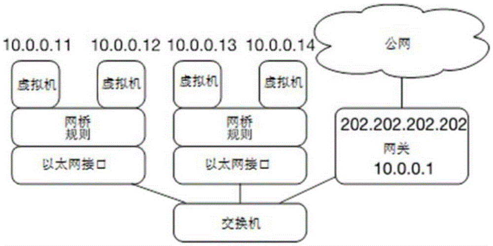
Technical field [0001] The embodiment of the present invention relates to data transmission technology, in particular to a multi-tenant-oriented cloud network architecture. Background technique [0002] Network management and configuration is a very important function in cloud computing technology. Realizing a flexible, efficient and secure network architecture has always been the goal pursued by various cloud platforms. [0003] Most of the existing public cloud network architectures or private cloud network architectures are solutions based on the open source cloud computing management platform Openstack community, including flat network architectures and network architectures based on overlay design. The above network architecture can meet the needs of use when deployed on a small scale or used internally. Then, as a commercial solution, there are obvious performance and security bottlenecks when facing large-scale tenants and facing Internet access. E.g, figure 1 Provides a f...

Claims


Application Information

Patent Timeline
IPC IPC(8): H04L29/08H04L12/707H04L12/733H04L45/122H04L45/24
CPCH04L45/20H04L45/24H04L67/10H04L67/1044
Inventor 张陵杨娜李雅妮段利平
Owner 北京云启志新科技股份有限公司
Learn More