Eureka AIR delivers breakthrough ideas for toughest innovation challenges, trusted by R&D personnel around the world.

Micro semi-ring female die array-mode lapping and polishing method and device

A semi-ring concave die and array technology, which is applied in the direction of grinding device, grinding machine tool, grinding tool, etc., to achieve the effect of low surface roughness, high efficiency and high shape consistency

Active Publication Date: 2016-03-02
ZHEJIANG UNIV OF TECH
View PDF7 Cites 26 Cited by
  • Summary
  • Abstract
  • Description
  • Claims
  • Application Information

AI Technical Summary

Problems solved by technology

[0003] In order to overcome the deficiencies that the existing resonant gyroscope micro-half ring dies cannot achieve high shape accuracy, low surface roughness, high surface quality, and high-efficiency processing, the present invention provides a high shape accuracy, low surface roughness, high surface quality , high-efficiency micro-semi-ring die array polishing method and device

Method used


Image

  • Micro semi-ring female die array-mode lapping and polishing method and device
  • Micro semi-ring female die array-mode lapping and polishing method and device
  • Micro semi-ring female die array-mode lapping and polishing method and device

Examples


Embodiment Construction

[0027] The present invention will be further described below in conjunction with the accompanying drawings.

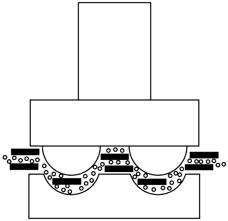
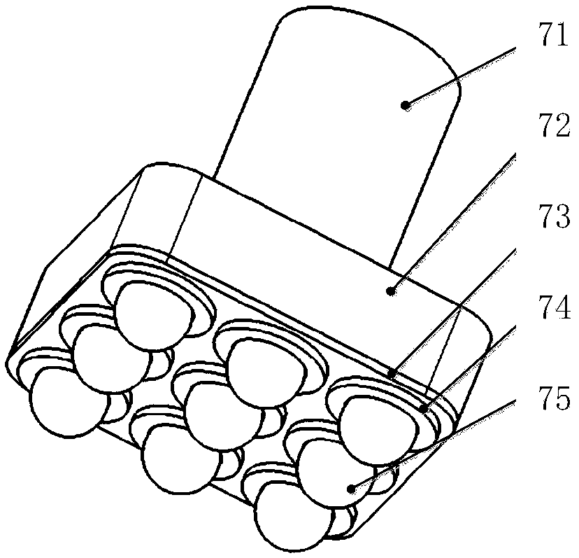
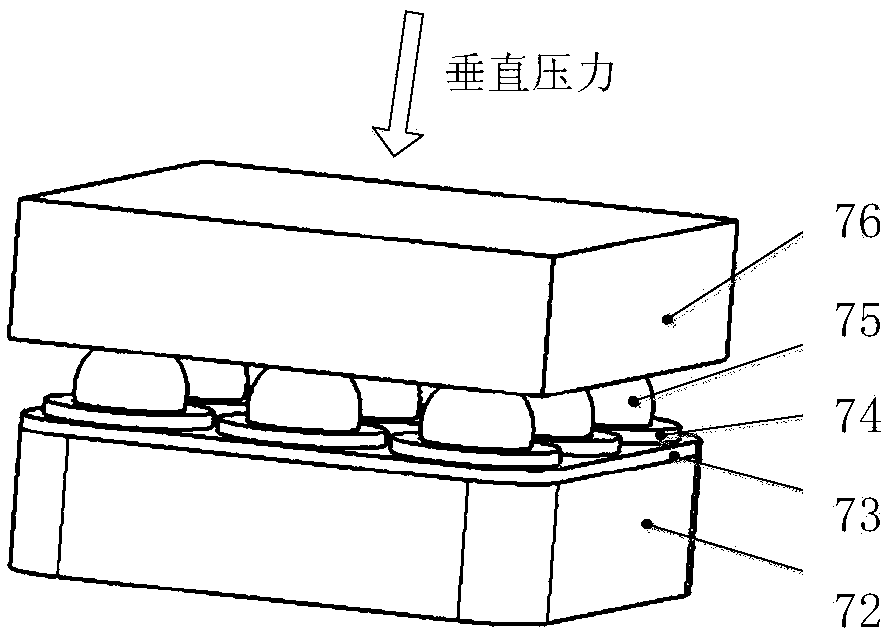
[0028] refer to Figure 1 to Figure 5 , a micro-semi-ring die array polishing method, the polishing method comprises the following steps:

[0029] 1) Making ultra-precision and high-consistency grinding and polishing molds

[0030] Described polishing mold comprises tool connecting rod 71, positioning base plate 72, precision sphere 75, and the upper end of tool connecting rod 71 is connected with fine ultrasonic generator, and the lower end of described tool connecting rod 71 is connected with positioning base plate 72, on positioning base plate An array of apertures is processed on 72, the aperture size is smaller than the diameter of the precision sphere, and the gap between the aperture and the precision sphere 75 is filled with adhesive, and a part of the sphere is embedded in the hole;

[0031] 2) The gap between the ultra-precision and high-consistency polishi...


PUM


Abstract

Disclosed is a micro semi-ring female die array-mode lapping and polishing method. The method includes the following steps that (1) a high-uniformity ultra-precise lapping and polishing die is manufactured, the upper end of a tool connecting rod is connected with a micro ultrasonic generator, the lower end of the tool connecting rod is connected with a positioning substrate, array apertures are formed in the positioning substrate, the size of the apertures is smaller than the diameter of precise spheres, spaces between the apertures and the precise spheres are filled with a binder, and part of the spheres is embedded into the apertures; and (2) the space between the high-uniformity ultra-precise lapping and polishing die and a substrate slice is filled with lapping and polishing liquid, the granularity of abrasive grains in the lapping and polishing liquid is nanoscale, the lapping and polishing die performs high-frequency micro ultrasonic vibration in the micro distance on the substrate slice, the ultrasonic vibration excites the abrasive grains in the lapping and polishing liquid to impact on the substrate slice at high speed, the lapping and polishing die performs feed movement downwards at set speed in the Z direction, and material removal of a micro semi-ring female die array is achieved. The invention further provides a micro semi-ring female die array-mode lapping and polishing device. The micro semi-ring female die array-mode lapping and polishing method and device can achieve the lapping and polishing effects of high efficiency, shape accuracy, shape uniformity and surface quality and low surface roughness.

Description

technical field [0001] The invention belongs to the field of ultra-precision machining, and relates to a microsemi-ring concave mold array polishing method and device. Background technique [0002] Hemispherical resonant gyroscope is a new type of inertial sensor, which has many advantages compared with mechanical gyroscope. The macro-scale hemispherical resonant gyroscope has reached the inertia level and has been applied to aviation, weapons and space inertial navigation systems. Its application is largely limited. MEMS gyroscopes have the advantages of small size, light weight, and low power consumption, but the existing MEMS gyroscopes cannot achieve inertial-level accuracy and higher tactical-level accuracy, and cannot be used in occasions that require high precision, such as providing aircraft in GPS blind areas. short range navigation. The main reason for the low accuracy of MEMS gyroscopes is that the existing MEMS component processing methods, such as chemical co...

Claims


Application Information

Patent Timeline
Patent Type & Authority Applications(China)
IPC IPC(8): B24B1/04B24B37/00B24B37/11B24B37/34
CPCB24B1/04B24B37/00B24B37/11B24B37/34
Inventor 袁巨龙赵军杭伟
Owner ZHEJIANG UNIV OF TECH
Why Eureka
Eureka Blog
Learn More