
Inverted organic electroluminescent device and preparation method thereof

An electroluminescent device, an inverted technology, which is applied in the fields of electro-solid devices, semiconductor/solid-state device manufacturing, electrical components, etc., can solve the problems of unconsidered optical performance of devices and the influence of optical performance of inverted devices, and achieves good optical effects. , The effect of good electron injection ability and cost saving

Active Publication Date: 2016-02-24
FIFTH ELECTRONICS RES INST OF MINIST OF IND & INFORMATION TECH +1
View PDF11 Cites 7 Cited by
  • Summary
  • Abstract
  • Description
  • Claims
  • Application Information

AI Technical Summary

Problems solved by technology

[0006] In the prior art, although the electron injection ability of the inverted OLED device has been improved to a certain extent, that is, the electrical performance of the device has been improved, but the optical performance of the device has not been considered
Especially with ZnO, TiO 2 Inorganic materials with a large difference in refractive index have not been considered when inserting the ITO cathode and electron transport layer as the electron injection layer.
[0007] It can be seen that the processing methods in the prior art generally have an impact on the optical performance of the inverted device

Method used


Image

  • Inverted organic electroluminescent device and preparation method thereof
  • Inverted organic electroluminescent device and preparation method thereof

Examples


Embodiment 1

[0028] ITO: indium tin oxide;

[0029] SiO 2 : silicon dioxide;

[0030] TiO 2 :Titanium dioxide

[0031] NPB: (N,N'-diphenyl-N,N'-(1-naphthyl)-1,1'-biphenyl-4,4'-diamine);

[0032] C545T: 2,3,6,7-tetrahydro-1,1,7,7-tetramethyl-1H,5H,11H-10-(2-benzothiazolyl)-quinazino[9,9A, 1GH] coumarin;

[0033] MADN: 2-methyl-9,10-bis(naphthalen-2-yl)anthracene

[0034] Alq 3 : aluminum octahydroxyquinoline;

[0035] Al: aluminum.

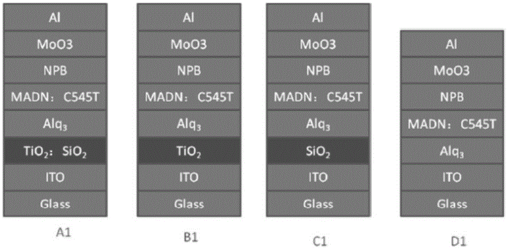
[0036] The structure of the prepared device A1 is: Glass (substrate) / ITO (cathode layer) / TiO 2 : SiO 2 (electron injection layer) / Alq 3 (electron transport layer) / MADN: C545T (green fluorescent light-emitting layer) / NPB (hole transport layer) / MoO3( hole injection layer) / Al (anode layer).

[0037] The optical refractive index of the electron injection layer is 1.78.

[0038] The preparation method is as follows:

[0039] After selecting the glass substrate, prepare the ITO cathode layer, TiO 2 : SiO 2 Electron injection layer, Alq ...

Embodiment 2

[0050] ITO: indium tin oxide;

[0051] ZnO: zinc oxide;

[0052] MgF2: magnesium fluoride

[0053] NPB: (N,N'-diphenyl-N,N'-(1-naphthyl)-1,1'-biphenyl-4,4'-diamine);

[0054] C545T: 2,3,6,7-tetrahydro-1,1,7,7-tetramethyl-1H,5H,11H-10-(2-benzothiazolyl)-quinazino[9,9A, 1GH] coumarin;

[0055] MADN: 2-methyl-9,10-bis(naphthalen-2-yl)anthracene

[0056] Alq 3 : aluminum octahydroxyquinoline;

[0057] Al: aluminum.

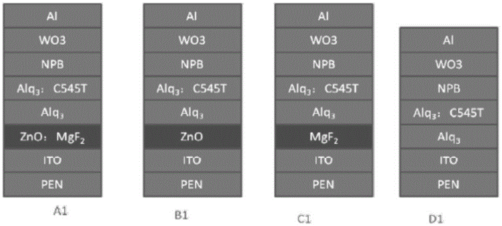
[0058] The structure of the prepared device A2 is: PEN (substrate) / ITO (cathode layer) / ZnO:MgF 2 (electron injection layer) / Alq 3 (electron transport layer) / Alq 3 : C545T (green fluorescent light-emitting layer) / NPB (hole transport layer) / WO3( hole injection layer) / Al (anode layer).

[0059] The optical refractive index of the electron injection layer is 1.82.

[0060] The preparation method is as follows:

[0061] After selecting the PEN substrate, prepare the ITO cathode layer, ZnO:MgF 2 Electron injection layer, Alq 3 electron transp...


PUM

PropertyMeasurementUnit
Thicknessaaaaaaaaaa
Thicknessaaaaaaaaaa

Abstract

The invention relates to an inverted organic electroluminescent device. The inverted organic electroluminescent device comprises a substrate, a cathode layer, an electron injecting layer, an organic function layer and an anode layer which are superposed in sequence. The organic function layer comprises an electron transmission layer, a luminescent layer, a cavity transmission layer and a cavity injecting layer which are superposed in sequence. The optical refractive index of the electron injecting layer is between those of the cathode layer and the electron injecting layer. The inverted organic electroluminescent device has the advantages that the electron injecting capability is good, the optical effect is good, a relatively small current is needed to achieve the same brightness, and the work voltage of the device is substantially lowered, so that the service lifetime of the device is greatly prolonged, the cost is saved, and the commercialization of the device is facilitated.

Description

technical field [0001] The invention relates to the technical field of organic semiconductors, in particular to an inverted organic electroluminescence device and a preparation method thereof. Background technique [0002] OLED (full name in English is OrganicLightEmittingDiodes, which means organic electroluminescent device, referred to as OLED) has self-illumination, wide viewing angle, light weight, wide temperature range, large area, full curing, flexibility, low power consumption, fast response speed and It has many advantages such as low manufacturing cost and has important applications in the fields of display and lighting, so it has attracted extensive attention from academia and industry. [0003] Traditional OLED devices generally adopt a positive structure. Generally, indium tin oxide (Indium Tin Oxide, ITO), indium zinc oxide (Indium Zinc Oxide, IZO), etc. are deposited on glass as transparent anodes, and metals with high reflectivity are used as cathodes, such a...

Claims


Application Information

Patent Timeline
IPC IPC(8): H01L51/50H01L51/56
CPCH10K71/12H10K50/171
Inventor 罗东向刘佰全黄林轶徐华伟胡坚耀范林勇黄庆礼贺致远陈玉明
Owner FIFTH ELECTRONICS RES INST OF MINIST OF IND & INFORMATION TECH
Learn More