Device for assessing extent of degradation in secondary cell

A secondary battery and judging device technology, applied to battery circuit devices, circuit devices, battery/fuel cell control devices, etc., can solve problems such as inability to directly measure OCV and difficulty in estimating OCV

Inactive Publication Date: 2016-02-17
HITACHI AUTOMOTIVE SYST LTD
View PDF8 Cites 15 Cited by
  • Summary
  • Abstract
  • Description
  • Claims
  • Application Information

AI Technical Summary

Problems solved by technology

[0005] Therefore, in order to obtain the correct SOC, it is necessary to accurately measure the OCV. However, when a large current flows through the secondary battery, the voltage corresponding to the resistance of the secondary battery will be affected, so the OCV cannot be directly measured. In addition, in the state where the current flows It is difficult to calculate the OCV at this moment

Method used


Image

  • Device for assessing extent of degradation in secondary cell
  • Device for assessing extent of degradation in secondary cell
  • Device for assessing extent of degradation in secondary cell

Examples


no. 1 approach

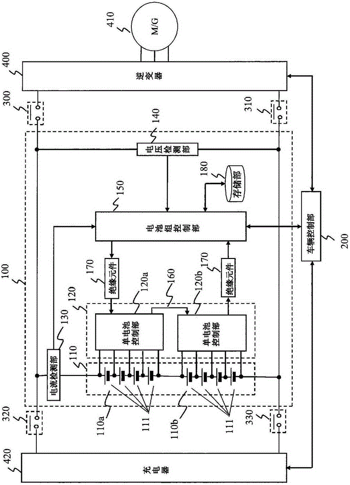
[0030] figure 1 It is a block diagram showing the circuit configuration of the battery system 100 and its periphery according to the embodiment of the present invention. Battery system 100 is connected to vehicle control unit 200 , and vehicle control unit 200 controls relays 300 and 310 to connect battery system 100 to inverter 400 . Furthermore, vehicle control unit 200 controls relays 320 and 330 to connect battery system 100 to charger 420 .

[0031] The battery system 100 includes a battery pack 110 , a cell control unit 120 , a current detection unit 130 , a voltage detection unit 140 , a battery pack control unit 150 , and a storage unit 180 .

[0032] The battery pack 110 is a secondary battery and is composed of unit cell groups 110 a and 110 b , and the unit cell groups 110 a and 110 b are each composed of a plurality of unit cells 111 .

[0033] The battery pack 110 is configured by electrically connecting a plurality of cells 111 capable of storing and dischargin...

no. 2 approach

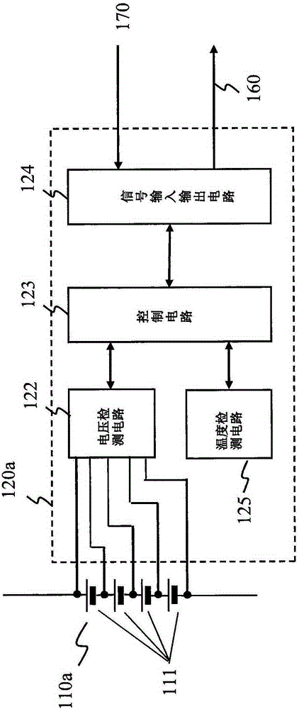
[0069] Next, a second embodiment of the present invention will be described. The block diagram and the circuit structure of the battery system 100 and its surroundings in the second embodiment figure 1 Similarly, the block diagram showing the circuit configuration of the cell control unit 120a is the same as figure 2 Since they are the same, the description of each block diagram is omitted.

[0070] refer to Figure 4 The operation of determining the degree of deterioration of the secondary battery according to the second embodiment of the present invention will be described.

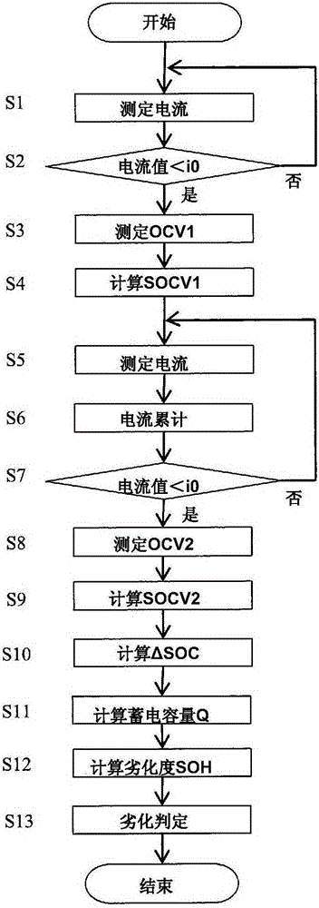
[0071] Figure 4 This is a flow chart for determining the degree of deterioration of the secondary battery. The processing operations shown in this flowchart are repeatedly executed by the battery pack control unit 150 at regular intervals or at regular intervals while the vehicle is running. image 3 The steps of the same processing operations as the steps shown in are denoted by the same symbols...

no. 3 approach

[0078] Next, a third embodiment of the present invention will be described. The block diagram and the circuit structure of the battery system 100 and its surroundings in the third embodiment figure 1 Similarly, the block diagram showing the circuit configuration of the cell control unit 120a is the same as figure 2 Since they are the same, the description of each block diagram is omitted.

[0079] refer to Figure 5 The operation of determining the degree of deterioration of the secondary battery according to the third embodiment of the present invention will be described.

[0080] Figure 5 This is a flow chart for determining the degree of deterioration of the secondary battery. The processing operations shown in this flowchart are repeatedly executed by the battery pack control unit 150 at regular intervals or at regular intervals while the vehicle is running. image 3 The steps of the same processing operations as the steps shown in are denoted by the same symbols an...


PUM


Abstract

This device for assessing the extent of degradation in a secondary cell is provided with: a detection unit for detecting whether the current value flowing to a secondary cell is below a predetermined value; a first voltage measurement unit that, from a start time of a predetermined period, which time is coincident with the point in time at which the current value flowing to a secondary cell was detected by the detection unit to be below a predetermined value, measures a first cell voltage of the secondary cell at the start time; a first charge level calculation unit for calculating a first charge level corresponding to the secondary battery, doing so on the basis of the measured first cell voltage; a second voltage measurement unit that, subsequent to measurement of the first cell voltage by the first voltage measuring unit, from an end time of a predetermined period, which time is coincident with the point in time at which the current value flowing to a secondary cell was detected by the detection unit to be below a predetermined value, measures a second cell voltage of the secondary cell at the end time; a second charge level calculation unit for calculating a second charge level corresponding to the secondary battery, doing so on the basis of the measured second cell voltage; a cumulative current amount calculation unit for calculating the cumulative current amount of electrical current that flowed to the secondary cell in the predetermined period; and a charged capacity calculation unit for calculating the differential of the first charge level and the second charge level, and dividing the cumulative current amount by the differential to calculate the charged capacity.

Description

technical field [0001] The present invention relates to a secondary battery deterioration degree judging device for judging the deterioration degree of a secondary battery. Background technique [0002] In general, chargeable and dischargeable secondary batteries represented by lithium-ion batteries and nickel-metal hydride batteries deteriorate due to repeated charge and discharge, and their storage capacity gradually decreases from the initial storage capacity. [0003] In equipment using secondary batteries, it is necessary to accurately grasp the current storage capacity of the secondary battery in order to estimate the operating time of the equipment, and in order to determine the life of the secondary battery and know when to replace it with a new secondary battery. capacity. The device is equipped with a system that compares the current storage capacity with the initial storage capacity of the secondary battery, and notifies the user of the device to replace the seco...

Claims


Application Information

Patent Timeline
Patent Type & Authority Applications(China)
IPC IPC(8): G01R31/36
CPCB60L2240/545B60L2240/547B60L2240/80B60L2260/44G01R31/3828B60L58/16B60L58/12G01R31/392G01R31/3842G01R31/396H02J7/0048Y02T10/70H02J7/0013H02J7/005
Inventor 五十岚直行大川圭一朗
Owner HITACHI AUTOMOTIVE SYST LTD
Why Eureka
Try Eureka