
Solid oxide fuel cell with anti-carbon function

A solid oxide and fuel cell technology, applied in solid electrolyte fuel cells, battery electrodes, circuits, etc., to achieve the effects of reducing deposition, increasing the amount of catalyst, and improving catalytic conversion efficiency

Active Publication Date: 2016-01-13
SHANXI UNIV
View PDF6 Cites 8 Cited by
  • Summary
  • Abstract
  • Description
  • Claims
  • Application Information

AI Technical Summary

Problems solved by technology

[0003] The object of the present invention is to provide a stable solid oxide fuel cell that can be used for hydrocarbon fuels and has an anti-carbon deposition function to solve the problem that the existing solid oxide fuel cell based on nickel anodes is easy to generate carbon deposits when it is applied to hydrocarbon fuels. oxide fuel cell

Method used


Image

  • Solid oxide fuel cell with anti-carbon function
  • Solid oxide fuel cell with anti-carbon function
  • Solid oxide fuel cell with anti-carbon function

Examples


Embodiment 1

[0030] Using the classic NiO-YSZ / YSZ / LSM-YSZ as a single cell, Al 2 O 3 As the substrate of the catalyst layer, NiO / BaO / CeO synthesized in a certain proportion 2 The mixture is the catalyst:

[0031] (1) Preparation of catalyst powder: according to Ni:BaO:CeO 2 The mass fraction is 13:2:85, respectively weigh nickel nitrate, barium nitrate, cerium nitrate, dissolve in deionized water, add glycine, and the molar ratio of glycine to total metal ions (G / M n+ ) is 3:1. Put it on an electric furnace to heat and stir, and after the water is evaporated to dryness, the primary powder is obtained by spontaneous combustion, and then placed in an oven at 240°C for 8 hours. After cooling, it was calcined in a muffle furnace at 850 °C for 2 h, and the heating rate was 5 °C min -1 .

[0032] (2) Preparation of catalyst layer: Weigh 0.3 g of Al with a mass ratio of 9:1 2 O 3 Mix the powder with PVB uniformly, press the catalyst layer substrate with a tableting die at 144MPa, and then...

Embodiment 2

[0038] Using NiO-YSZ / YSZ / LSM-YSZ as a single cell and YSZ as a catalyst substrate, the synthesized NiO / BaO / CeO 2 for catalyst:

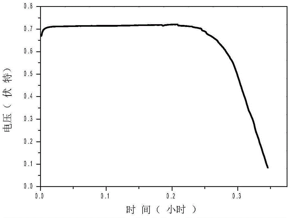
[0039] The preparation method is the same as in Example 1, except that the Al in Example 1 2 O 3 Replace with YSZ, see battery discharge life Figure 5 .

Embodiment 3

[0041] Using NiO-YSZ / YSZ / LSM-YSZ as a single cell, Al 2 O 3 As a catalyst substrate, NiO / BaO / CeO synthesized in a certain proportion 2 / Al 2 O 3 for catalyst:

[0042] (1) Preparation of catalyst powder: Ni:BaO:CeO 2 :Al 2 O 3 The mass fraction is 13:2:42.5:42.5. Weigh nickel nitrate, barium nitrate, cerium nitrate, aluminum nitrate, dissolve in deionized water, add glycine, and the molar ratio of glycine to metal ions (G / M n+ ) ratio is 3:1. Put it on an electric furnace to heat and stir, and after the water is evaporated to dryness, it will spontaneously ignite to obtain a primary powder, and put it in an oven to dry at 240°C for 8 hours. After cooling, it was calcined in a muffle furnace at 850 °C for 2 h, and the heating rate was 5 °C min -1 .

[0043] (2)-(5) are the same as in Example 1, the constant current discharge life of the battery is shown in Image 6 .


PUM


Abstract

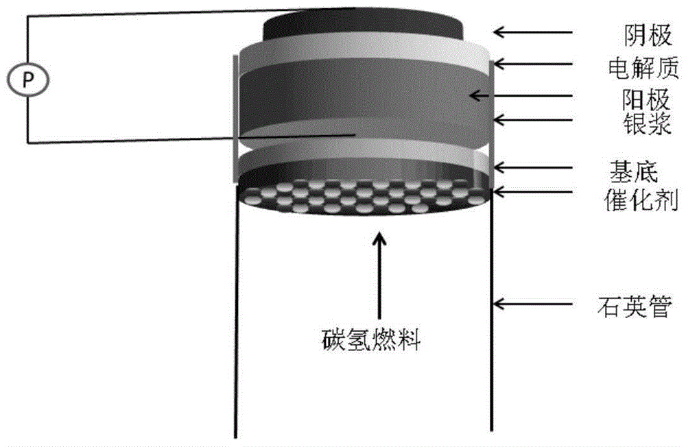
The invention provides a solid oxide fuel cell with an anti-carbon function, and belongs to the solid oxide fuel cell based on a nickel positive electrode. The solid oxide fuel cell comprises an anode, an electrolyte, a cathode and a quartz airway tube; the solid oxide fuel cell is characterized in that an independent catalyst layer is arranged in the anode side; the catalyst layer comprises a base and a catalyst; the base material is an oxide material with high rigidity; and the catalyst is a material having high oxidation catalyst activity on hydrocarbon fuels. According to the solid oxide fuel cell with the anti-carbon function, the problem of cell expansion-cracking caused by unmatched thermal expansion of the catalyst and the anode is solved, and the carbon deposition of the anode is restrained effectively, so that the stability and the reliability of the solid oxide fuel cell are greatly improved.

Description

technical field [0001] The present invention relates to a chemical power source, in particular to a solid oxide fuel cell based on a nickel anode, and more particularly to a solid oxide fuel cell with anti-carbon deposition function. Background technique [0002] Solid oxide fuel cell (SOFC) has the advantages of high energy conversion efficiency, wide range of fuel applications, and no pollution, making it a new generation of fuel cells that can be used in stationary power stations, vehicle auxiliary power sources, and small mobile power sources. Due to its high electrochemical activity, high electronic conductivity, good stability, and low price, nickel-based ceramic composite anodes exhibit stable performance when using hydrogen as fuel, and are still the most commonly used anode materials so far. However, given the technical limitations in hydrogen production, storage, and transportation, hydrogen-fueled SOFCs are unlikely to be widely used in the next few years. Since ...

Claims


Application Information

Patent Timeline
IPC IPC(8): H01M8/12H01M4/90H01M4/88
CPCH01M4/8864H01M4/9025H01M8/12Y02E60/50Y02P70/50
Inventor 陈绘丽王芬常宏李思殿
Owner SHANXI UNIV
Learn More