
Automatic target scoring and speed measuring device and positioning and speed measuring method thereof

An automatic, target-surface technology, applied in the direction of targets, target indication systems, weapon accessories, etc., can solve the problems of complex signal processing algorithms, high cost of use, limited sensitivity, etc., to avoid trigonometric function calculations, low installation accuracy requirements, and simplified The effect of hardware and software structure

Active Publication Date: 2015-12-23
NO 709 RES INST OF CHINA SHIPBUILDING IND CORP
View PDF12 Cites 18 Cited by
  • Summary
  • Abstract
  • Description
  • Claims
  • Application Information

AI Technical Summary

Problems solved by technology

Among them, the ultrasonic shock wave method uses the shock wave generated when the projectile flies at supersonic speed or the ultrasonic wave generated by the projectile to break down the target material for detection. The former, such as the shock wave target reporting system with the patent number CN200610102134.X, requires that the projectile must be a supersonic projectile , can not detect some pistols with low projectile velocity; the latter, such as the multi-channel automatic target reporting system for ultrasonic electronic target live ammunition shooting with patent No. CN201010231582. Embedded hardware implementation
The double-layer electrode short-circuit sampling method uses two layers of conductive layers to sandwich an insulating layer to make the target material, and the corresponding point is turned on for detection when a projectile passes through, such as a device for automatic target reporting for light weapon live ammunition shooting with patent number CN201310077701.0 And its working method, the disadvantage is that the target material is more expensive and the cost of use is high
The laser tube or light curtain method uses the laser tube or optical fiber to form an optical grid, and when a projectile passes through, it blocks the optical grid and is detected. For example, the patent No. CN200710019000.6 is the light curtain array automatic target reporting device and method, The disadvantage is that the production and installation of the light curtain requires high precision, so the cost is expensive, and the receiver tube can also be replaced by a camera or a linear array CCD, but the sensitivity is limited and the exposure time is long, resulting in poor detection performance for high-speed projectiles
Image processing method, such as the patent No. CN201310249220.3, is a kind of automatic shooting target reporting system based on image recognition. The camera shoots the target surface for image processing, and obtains the position of the impact point. Degraded detection performance when required and coincident with bullet points

Method used


Image

  • Automatic target scoring and speed measuring device and positioning and speed measuring method thereof
  • Automatic target scoring and speed measuring device and positioning and speed measuring method thereof
  • Automatic target scoring and speed measuring device and positioning and speed measuring method thereof

Examples


Embodiment 1

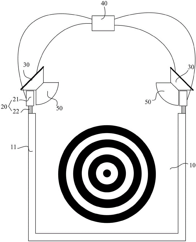
[0047] Such as figure 1 As shown, Embodiment 1 of the present invention provides an automatic target reporting device, which includes,

[0048] Target surface 10, on which target material and target paper are laid sequentially on the target surface 10;

[0049] A linear continuous infrared background light source 20 is installed around at least three edges of the target surface 10;

[0050]At least two first-type optical sensors 30 connected to the main control board 40, the at least two first-type optical sensors 30 are respectively installed on the top corners of the target surface 10, so that the first-type optical sensors 30 can be The viewing range covers the entire target surface 10;

[0051] The main control board 40 is electrically connected with the first-type optical sensor 30, and is used to receive the data collected by the first-type optical sensor 30, and obtain the geometric coordinates of the impact point through analysis and calculation. The specific compos...

Embodiment 2

[0103] Embodiment 2 of the present invention such as Figure 14 Shown, a kind of automatic speed measuring device, it comprises,

[0104] Two target surfaces 10 arranged side by side;

[0105] Each target surface 10 is respectively provided with a linear continuous infrared background light source 20, and the linear continuous infrared background light source 20 is respectively installed around at least three edges of each target surface 10;

[0106] Each of the two ends of the linear continuous infrared background light source 20 is respectively connected with at least two first-type optical sensors 30 on the optical path, and the at least two first-type optical sensors 30 are respectively installed on the vertex of the target surface 10, so that The visible range of the first type of optical sensor 30 covers the entire target surface 10;

[0107] The second-type optical sensor 60 installed directly above each target surface 10 also has a visible range covering the entire t...


PUM

PropertyMeasurementUnit
Center wavelengthaaaaaaaaaa
Opening angleaaaaaaaaaa
Viewing angleaaaaaaaaaa

Abstract

The invention provides an automatic target scoring and speed measuring device and a positioning and bullet speed measuring method. At least two first-class optical sensors are used for detecting the position of a point of impact, and bullets of various types and speeds except light tracers can be accurately positioned; moreover, linear and continuous infrared background light sources are adopted, so that light intensity of all portions of a target surface is evenly distributed, in the bullet point coordinate positioning process, a method including optical calibration table checking and ratio calculation is adopted, trigonometric function operation of a triangulation localization method is avoided, hardware calculation is easy to achieve, and the software and hardware structure is simplified. Meanwhile, two automatic target scoring devices with second-class optical sensors are used and connected in series to form an automatic speed measuring device, and under the condition of no target and target paper, the speed of a bullet of common light arms and a cannon can be measured. The automatic target scoring and speed measuring device and the positioning and bullet speed measuring method thereof are high in measuring precision, low in installation precision requirement, easy to maintain and suitable for wide application.

Description

technical field [0001] The invention relates to an automatic target reporting device, in particular to an automatic target reporting and speed measuring device and a positioning and speed measuring method thereof. Background technique [0002] There are two types of target reporting: chest ring target and coordinate target. The former only requires the reporting of the number of impact points, which is used in various training, competition and entertainment facilities; the latter also requires reporting the precise geometric coordinates of the impact point, which is generally used for adjusting the accuracy of light weapons. Traditional manual target reporting takes up manpower, is not safe, low in efficiency, and cannot detect bursts. Therefore, various automatic target reporting systems have appeared in recent years, but there are often problems of high purchase and use costs, inconvenient use, and the impact point Problems such as many and overlapping, error-prone, compl...

Claims


Application Information

Patent Timeline
IPC IPC(8): F41J5/02F42B35/02
Inventor 王珩田传东张怀邵宏峰
Owner NO 709 RES INST OF CHINA SHIPBUILDING IND CORP
Learn More