
A wave rotor cascade refrigeration system and its working method

A technology of refrigeration system and wave rotor, which is applied in the field of wave rotor cascade refrigeration system, can solve the problems that hinder the wide application of R718 refrigerant, and achieve the effects of excellent liquid-filled operation performance, low speed, and easy development

Active Publication Date: 2017-12-26
艾肯(江苏)工业技术有限公司
View PDF1 Cites 0 Cited by
  • Summary
  • Abstract
  • Description
  • Claims
  • Application Information

AI Technical Summary

Problems solved by technology

At present, although R718 can be used in vapor compression refrigeration systems, this R718 compressor has a much larger compression ratio (twice that of R134a) and a large volume, high speed, and large displacement equipment size than conventional refrigerants, which seriously hinders Wide application of R718 refrigerant in vapor compression refrigeration system

Method used


Image

  • A wave rotor cascade refrigeration system and its working method
  • A wave rotor cascade refrigeration system and its working method
  • A wave rotor cascade refrigeration system and its working method

Examples


Embodiment 1

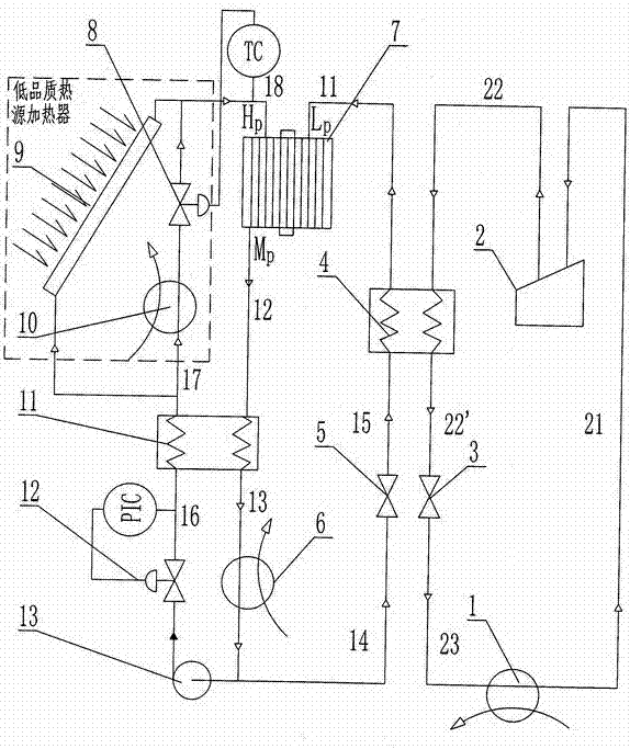
[0019] Embodiment 1 A wave rotor cascade refrigeration system utilizing solar energy as a heat source.

[0020] figure 1 A solar wave rotor cascade refrigeration system is shown. In the figure, the solar wave rotor cascade refrigeration system includes an evaporator 1, a low temperature compressor 2, a low temperature throttle valve 3, a condensation evaporator 4, a high temperature throttle valve 5, a cooler 6, a wave rotor 7, a temperature regulating valve 8, Heat collector 9, electric heater 10, regenerator 11, pressure regulating valve 12, booster pump 13. The outlet of the evaporator 1 is connected to the inlet of the cryogenic compressor 2, the outlet of the cryogenic compressor 2 is connected to the hot end inlet of the condensing evaporator 4, and the hot end outlet of the condensing evaporator 4 is connected to the inlet of the low temperature throttle valve 3, The outlet of the low-temperature throttle valve 3 is connected to the inlet of the evaporator 1; the outl...

Embodiment 2

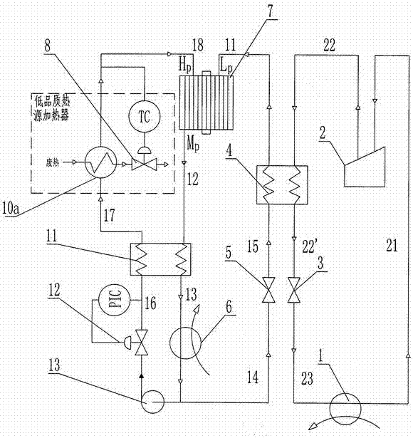
[0023] Example 2 A wave rotor cascade refrigeration system using waste heat as a heat source.

[0024] figure 2 A waste heat wave rotor cascade refrigeration system is shown. figure 2 and figure 1 The difference is that: the outlet of the regenerator 11 is connected to the inlet of the waste heat heater 10a, and the outlet of the waste heat heater 10a is connected to the driving steam inlet H of the rotor 7 P connect. The rest of the principles and equipment arrangement remain basically the same.

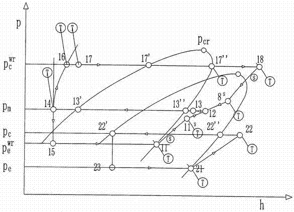
[0025] The low-temperature refrigerant absorbs heat at a constant temperature and constant pressure in the evaporator 1 to achieve refrigeration, becomes saturated steam and enters the low-temperature compressor 2, and the formed high-temperature and high-pressure gas passes through the condensing evaporator 4 and then passes through the low-temperature throttle valve in a saturated liquid state to reduce temperature and pressure Enter evaporator 1; outlet M of pressurized ste...


PUM


Abstract

A wave rotor cascade refrigeration system and its working method belong to the technical field of mechanical refrigeration. The high-temperature circulation device of the wave rotor cascade refrigeration system is composed of a flash wave rotor and a low-quality heat source heater, which can make full use of the waste heat of the low-quality heat source to achieve energy saving. The low-temperature refrigerant enters the low-temperature compressor for boosting after passing through the evaporator, and after being condensed by the condensing evaporator, it passes through the low-temperature throttling valve to reduce the temperature and pressure; the high-temperature refrigerant is divided into two streams after passing through the cooler, and one stream passes through the booster pump and the pressure regulating valve. , regenerator, low-quality heat source heater and temperature regulating valve enter the flash wave rotor, and the other stream enters the condensing evaporator after being lowered in temperature and pressure by the high-temperature throttle valve, and then enters the flash wave rotor to complete the pressurization process. into the cooler after the heater. The system's high-temperature refrigeration cycle can use low-quality heat sources such as solar energy, and the low-temperature cycle can be cascaded with energy-saving effects compared with conventional cascade systems.

Description

technical field [0001] The invention relates to a wave rotor cascade refrigeration system and a working method thereof, belonging to the technical field of mechanical refrigeration. Background technique [0002] With the rapid development of the national economy, the demand for low temperature below -50 ℃ is increasing, so the cascade refrigeration system is widely used in various fields. The simplest cascade refrigeration system usually consists of a high-temperature part and a low-temperature part. The high-temperature part uses medium-temperature refrigerants, such as R22, R717, R134a, R404A and R290, etc., and the low-temperature part uses low-temperature refrigerants, such as R23 and R744. Water (R718), as a natural refrigeration and refrigerant, has high latent heat, non-toxic, non-flammable, non-explosive and environmentally friendly characteristics (global warming index GWP=0, ozone depletion potential value ODP=0), especially R718 The theoretical energy efficiency ...

Claims


Application Information

Patent Timeline
Patent Type & Authority Patents(China)
IPC IPC(8): F25B7/00F25B27/02
CPCY02A30/274
Inventor 代玉强胡大鹏赵顶刘航朱彻邹久朋陶盛洋
Owner 艾肯(江苏)工业技术有限公司
Learn More