
Stone material line polisher and polishing method thereof

A technology of polishing machine and stone, which is applied in surface polishing machine tools, grinding/polishing equipment, and machine tools suitable for grinding the edge of workpieces, etc. It can solve problems such as poor working environment, affecting polishing effect, and difficulty in taking out stones. achieve a high degree of automation

Active Publication Date: 2015-12-02
湖南省恒鑫新材料科技有限公司
View PDF12 Cites 15 Cited by
  • Summary
  • Abstract
  • Description
  • Claims
  • Application Information

AI Technical Summary

Problems solved by technology

[0002] The current stone line processing is formed by grinding with a diamond wheel on the edging machine, and then using a resin grinding wheel for rough grinding, fine grinding, fine grinding, and polishing. The entire stone processing process is called polishing in the field, but in use Before grinding the grinding wheel, it is first necessary to trim a set of grinding wheels and match the shape of the lines produced by the diamond wheel grinder. It will take a lot of time to trim a set of grinding wheels, and the grinding lines will be deformed, and the finish is not high. The polishing speed of the grinding wheel is high, so dry grinding is generally used, resulting in a large amount of dust, resulting in a poor working environment, seriously affecting the health of the staff, and the work efficiency is still very low
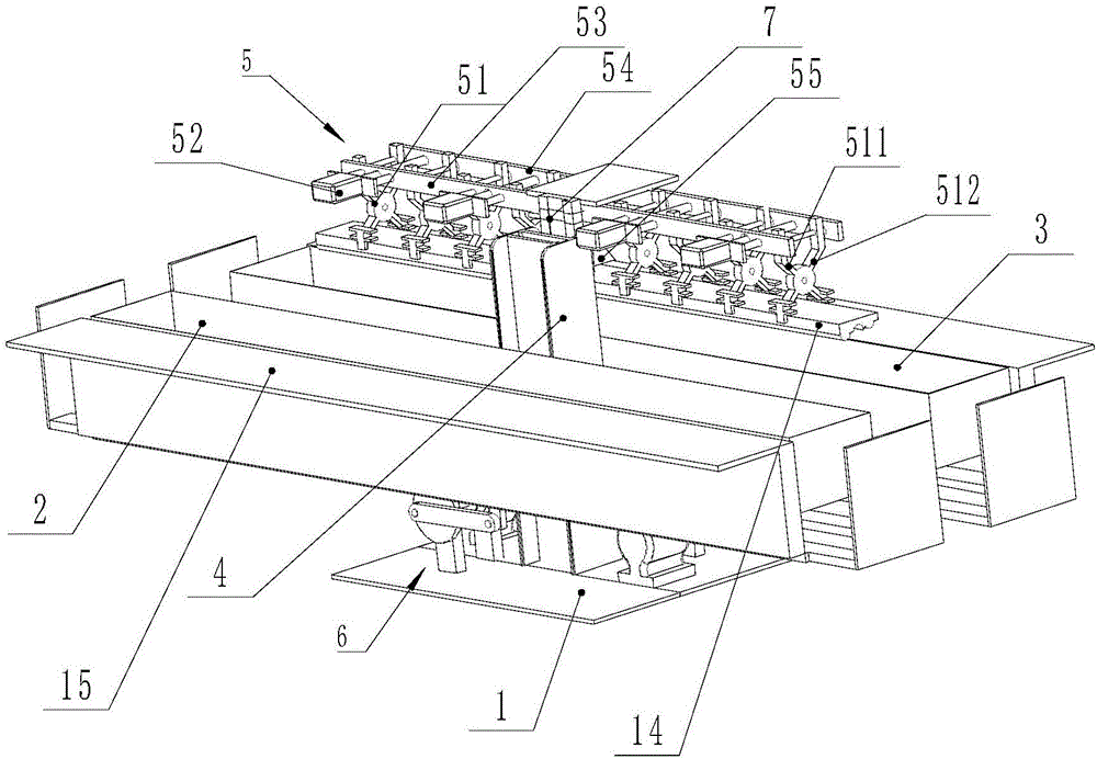
In order to solve the above problems, the applicant developed a stone line polishing device and applied for a patent, the patent number is: ZL201520239067.0, but although this polishing device solves the above problems, it still has the following disadvantages: 1. The polishing device The degree of automation is not high, especially when multiple grinding steps are required, such as rough grinding, fine grinding, fine grinding, and polishing, automatic continuous steps cannot be realized; 2. After a stone is polished by the polishing device, the stone needs to be taken out , because the stone will be pressed into the abrasive during polishing, it is very difficult to take out the polished stone, and it needs to be manually inserted into the abrasive to take it out, which is time-consuming and laborious
3. When the polishing device polishes the stone, it only limits the two ends of the length of the stone to avoid the vertical movement of the stone, but does not limit the horizontal direction of the stone, so there may be lateral movement during the movement, so will affect the polishing effect

Method used


Image

  • Stone material line polisher and polishing method thereof
  • Stone material line polisher and polishing method thereof
  • Stone material line polisher and polishing method thereof

Examples


Embodiment 1

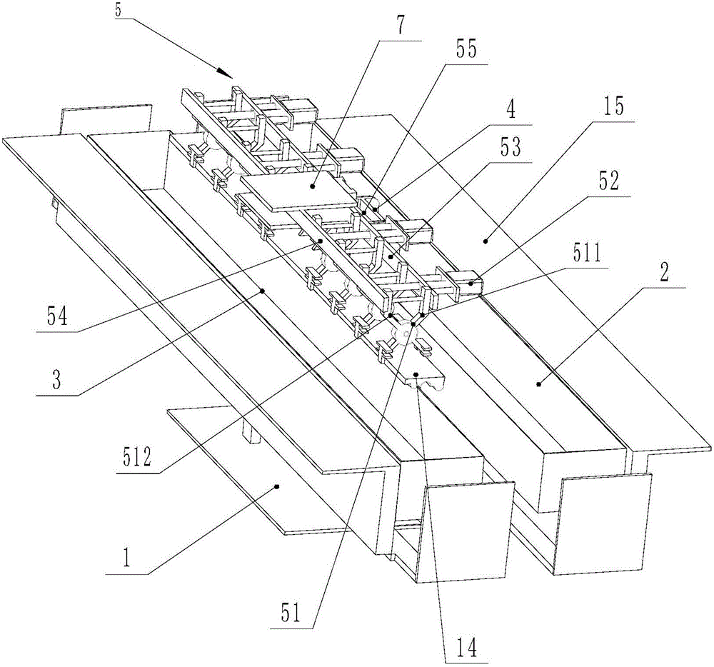
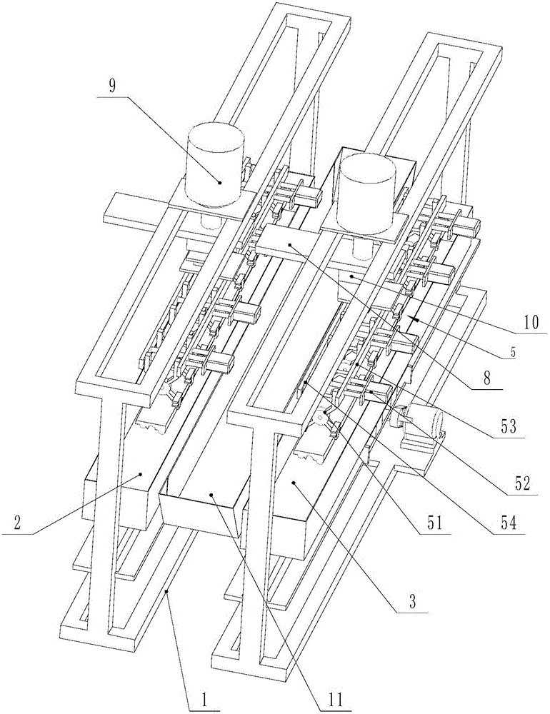
[0034] Such as figure 1As shown, a stone line polishing machine includes a frame 1, a trough is installed on the frame 1, and abrasive materials for contacting and polishing the surface of the stone to be polished are filled in the trough: the stone can be marble or For other stone materials that need to be polished and polished, the trough can be made of wear-resistant materials. The frame 1 is also vertically slidably equipped with a vertical slide seat 7, and the vertical slide seat 7 and the vertical drive device 9 Connected, the vertical drive device 9 can be driven by a cylinder or a linear motor, and the vertical slide 7 is equipped with a clamping assembly 5 for laterally clamping or loosening the stone, and the clamping assembly 5 clamps the stone in the trough Among them, the trough is driven to reciprocate and slide longitudinally by the horizontal reciprocating drive device 6 or the clamping assembly 5 is driven to reciprocate and slide longitudinally by the horizo...

Embodiment 2

[0045] Such as image 3 , Figure 4 As shown, this embodiment is also improved on the basis of the most basic solution described in embodiment 1.

[0046] In this solution, at least two feed troughs arranged side by side are installed on the frame 1, and the preferred feed chute is horizontally reciprocating at this time, and the number of vertical sliding seats 7 on the described frame 1 matches the number of feed troughs , each vertical sliding seat 7 is equipped with a horizontal and horizontal telescopic block 8, each telescopic block 8 is driven by a telescopic power device, and the telescopic power device can be a cylinder or other linear power device, each telescopic block 8 The clamping assembly 5 is installed through the connecting seat 10, and each telescopic power device drives the clamping assembly 5 on the corresponding telescopic block 8 to reciprocate and slide between its corresponding trough and the adjacent trough on the same side . That is to say, the tel...

Embodiment 3

[0051] This embodiment has been changed on the basis of embodiment 2,

[0052] Such as Figure 5 and Figure 6 As shown, the telescopic block 8 is also used to realize the material fetching from the adjacent trough on the same side, but the clamping assembly 5 adopts a manual clamping mode, and a movable clamp is used between the clamping assembly 5 and the telescopic block 8 Clamping or disengagement is achieved by disassembling the connection, and each clamping assembly 5 is connected to the telescopic block 8 through a quick connection mechanism, which realizes quick connection or separation between the clamping assembly 5 and the telescopic block 8 . The quick connection mechanism includes a clamped seat 13 arranged on the clamping assembly 5 , and the telescopic block 8 is provided with a clamping mechanism 12 for clamping or releasing the clamped seat 13 . The clamping mechanism 12 includes two clamping blocks 121 that cooperate with each other to clamp the clamped se...


PUM


Abstract

The invention discloses a stone material line polisher. The stone material line polisher comprises a rack. Material troughs are installed on the rack. Abrasive used for conducting contact polishing on the face to be polished of stone material is contained in the material troughs. A vertical slide seat is further installed on the rack vertically in a sliding mode. The vertical slide seat is connected with a vertical driving device. A clamping assembly transversely clamping or unclamping the stone material is installed on the vertical slide seat. The stone material clamped by the clamping assembly is located in the material troughs. The material troughs are driven by a horizontal reciprocating driving device to slide longitudinally in a reciprocating mode, or the clamping assembly is driven by the horizontal reciprocating driving device to slide longitudinally in a reciprocating mode. According to the polisher, rapid polishing of the stone material can be achieved, and meanwhile, rapid discharge is further achieved.

Description

technical field [0001] The invention relates to a stone line polishing machine, and also relates to a polishing method of the polishing machine. Background technique [0002] The current stone line processing is formed by grinding with a diamond wheel on the edging machine, and then using a resin grinding wheel for rough grinding, fine grinding, fine grinding, and polishing. The entire stone processing process is called polishing in the field, but in use Before grinding the grinding wheel, it is first necessary to trim a set of grinding wheels and match the shape of the lines produced by the diamond wheel grinder. It will take a lot of time to trim a set of grinding wheels, and the grinding lines will be deformed, and the finish is not high. The polishing speed of the grinding wheel is high, so dry grinding is generally used, resulting in a large amount of dust, resulting in a poor working environment, seriously affecting the health of the staff, and at the same time, the wo...

Claims


Application Information

Patent Timeline
IPC IPC(8): B24B31/00B24B41/06B24B27/00
CPCB24B27/0023B24B31/006B24B41/06
Inventor 陈楚均
Owner 湖南省恒鑫新材料科技有限公司
Learn More