Electro-hydraulic power braking system for automobile

An electronically controlled hydraulic and braking system technology, applied in the direction of brakes, brake transmissions, vehicle components, etc., can solve the problems of ball check valve wear and sticking in the pump, large pedal force, etc., and achieve convenient troubleshooting and design Reasonable and novel structure effect

Inactive Publication Date: 2015-11-04
HUAIYIN INSTITUTE OF TECHNOLOGY
View PDF4 Cites 7 Cited by
  • Summary
  • Abstract
  • Description
  • Claims
  • Application Information

AI Technical Summary

Problems solved by technology

For vehicles with diesel engines and gasoline direct injection engines designed to meet higher emission environmental protection requirements, since the vacuum pressure corresponding to the operating conditions of the engine cannot be provided at the intake pipe to meet the requirements of the vacuum-assisted hydraulic braking system, For diesel engines and gasoline direct injection engines, vacuum pumps are generally used to provide vacuum sources, but after the vacuum pumps have been used for a period of time, the spherical check valve in the pump will be stuck between the vacuum pump and the vacuum booster due to wear and tear. Disabling the vacuum booster resulting in high pedal effort when braking

Method used


Image

  • Electro-hydraulic power braking system for automobile
  • Electro-hydraulic power braking system for automobile
  • Electro-hydraulic power braking system for automobile

Examples


Embodiment Construction

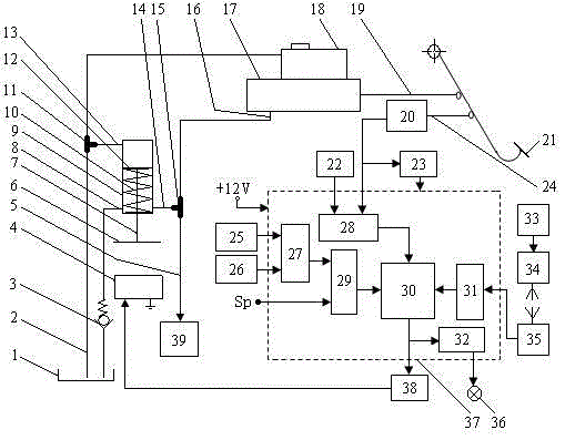
[0017] Such as figure 1 As shown, the automotive electronically controlled hydraulic power-assisted braking system includes a signal sensing part, a calculation and control unit and a signal execution part.

[0018] The signal sensing part includes a displacement sensor 20, a vehicle speed sensor 25, a wheel speed sensor 26, a tire pressure and tire temperature sensor 33, a signal transmitter 34, a signal receiver 35, a time signal generator 22, and a trigger 23. The linkage lever 24 is connected to the brake pedal 21, the signal of the wheel speed sensor 26 and the signal of the vehicle speed sensor 25 are connected to the calculation and control unit 37 through a wire, one signal of the displacement sensor 20 is directly connected to the calculation and control unit 37 through a wire, and the other signal is through the trigger 23 is connected to the calculation and control unit 37, the signal of the tire pressure and tire temperature sensor 33 is sent wirelessly by the sign...


PUM


Abstract

The invention discloses an electro-hydraulic power braking system for an automobile. The braking system comprises a signal sensing part, a calculating and controlling unit and a signal executing part, wherein a displacement sensor is connected with a brake pedal through a linkage rod; signals of the displacement sensor, a time signal generator, a wheel speed sensor and an automobile speed sensor are input into the calculating and controlling unit so as to calculate accelerated speed of the brake pedal and a wheel real-time slip ratio; a signal of a tire pressure and tire temperature sensor is input into the calculating and controlling unit through a signal transmitter and a signal receiver so as to calculate tire load coefficient; the calculating and controlling unit is used for controlling the value of the current of an input current amplifier according to the calculating result; under an effect of electromagnetic attraction forces generated by an electromagnetic coil and an iron core component, an armature is used for driving a piston to move down; and oil of both a power cylinder and a braking cylinder rapidly flows into a brake wheel cylinder so that the braking of the automobile is realized. The electro-hydraulic power braking system for the automobile, disclosed by the invention, is advantaged in that a brake power effect can be provided to a hydraulically-braked automobile; the braking is convenient and fast; the braking distance is reduced; and the safety of the automobile in running is improved.

Description

technical field [0001] The invention relates to an electronically controlled hydraulic power-assisted braking system for automobiles, which is suitable for all vehicles adopting hydraulic braking. Background technique [0002] With the continuous and rapid development of my country's economy, the continuous improvement of road traffic conditions and the steady improvement of people's consumption levels, the number of domestic car ownership has increased rapidly. At the same time, traffic accidents caused by cars are also increasing. People's health and property safety under greater threat. [0003] Automobile braking system is an important part of the automobile, its performance directly affects the driving safety of the automobile. In order to reduce the driver's operating intensity and ensure the safety of the car, the braking system is usually equipped with a booster device. At present, the most widely used hydraulic brake system in automobiles is the vacuum booster devic...

Claims


Application Information

Patent Timeline
Patent Type & Authority Applications(China)
IPC IPC(8): B60T13/66
CPCB60T13/662
Inventor 徐礼超
Owner HUAIYIN INSTITUTE OF TECHNOLOGY
Why Eureka
Try Eureka