Cooling device for brake

A technology for cooling devices and brakes, which is applied to the types of brakes, axial brakes, parts of brakes, etc., can solve the problems of obvious heat dissipation, high production costs, and high maintenance costs, and achieve promotion, simple processing, and low maintenance costs Effect

Inactive Publication Date: 2018-08-24
广德盛源电器有限公司
View PDF5 Cites 5 Cited by
  • Summary
  • Abstract
  • Description
  • Claims
  • Application Information

AI Technical Summary

Problems solved by technology

The brake disc and heat dissipation device in the disc brakes currently on the market are integrated, resulting in difficult processing, high production costs, high maintenance costs, and the heat dissipation effect is not obvious. Now a disc that separates the heat dissipation device from the brake disc is needed. disc brakes to fill the void left by low-cost disc brakes

Method used


Image

  • Cooling device for brake
  • Cooling device for brake
  • Cooling device for brake

Examples


Embodiment Construction

[0018] The following will clearly and completely describe the technical solutions in the embodiments of the present invention with reference to the accompanying drawings in the embodiments of the present invention. Obviously, the described embodiments are only some, not all, embodiments of the present invention. Based on the embodiments of the present invention, all other embodiments obtained by persons of ordinary skill in the art without making creative efforts belong to the protection scope of the present invention.

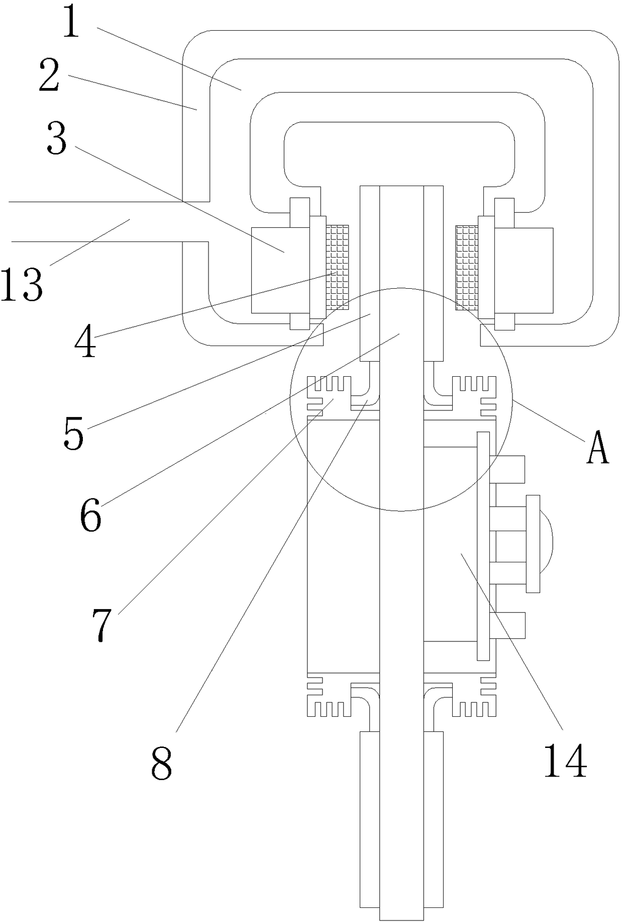
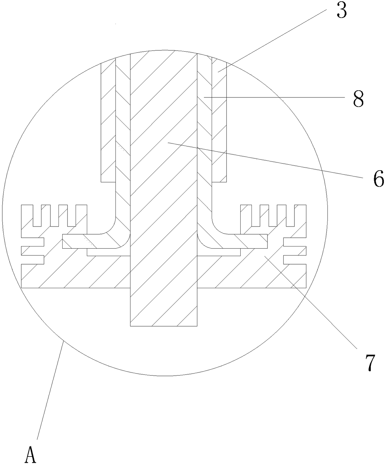
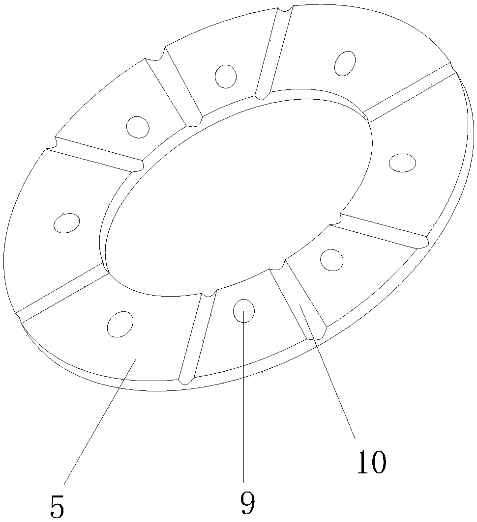
[0019] see Figure 1~5 , the present invention provides a technical solution: a brake cooling device, including a brake caliper housing 2 and a brake disc 6, the left side of the brake caliper housing 2 is provided with an oil inlet 13, and the brake caliper The housing 2 is provided with a hydraulic oil channel 1 communicating with the oil inlet 13. The lower end of the brake caliper housing 2 is slidingly connected with two mutually symmetrical pistons 3, an...


PUM


Abstract

The invention discloses a cooling device for a brake. The cooling device for the brake comprises a brake caliper shell and a brake disc. An oil inlet is formed in the left side of the brake caliper shell. A hydraulic oil passage which communicates with the oil inlet is arranged in the brake caliper shell. Two pistons which are arranged symmetrically with each other are sliably connected to the lower end of the brake caliper shell. Friction blocks are fixedly connected to the inner sides of the pistons. The outer sides of the pistons are arranged in the hydraulic oil passage. The brake disc isarranged under the brake caliper shell, and the upper end of the brake disc is located between the two pistons. Friction plates are tightly and fixedly connected to the two sides of the brake disc. Heat dissipation rings are arranged below the friction plates. Heat dissipation rings are connected with the friction plates through heat conduction wires. The heat dissipation rings are fixedly connected to the side surface of the brake disc. The brake disc is connected to a rotating shaft of a driving wheel through a flange. According to the cooling device for the brake, the structure is simple, the practicability is high, the heat dissipation effect is remarkable, the machining is simple, the maintenance cost is low, and popularization is facilitated.

Description

technical field [0001] The invention relates to the design field of brake cooling devices, in particular to a brake cooling device. Background technique [0002] A brake is a device that has the functions of decelerating, stopping or keeping a moving part (or moving machinery) in a stopped state. It is a mechanical part that stops or slows down the moving parts in the machine. Commonly known as brakes, brakes. The brake is mainly composed of frame, brake parts and operating device. Some brakes are also equipped with an automatic adjustment device for the clearance of the brake parts. In order to reduce the braking torque and structural size, the brake is usually installed on the high-speed shaft of the equipment, but for large-scale equipment with high safety requirements (such as mine hoists, elevators, etc.), it should be installed on the low-speed shaft close to the working part of the equipment. superior. [0003] Among them, the rotating element in the disc brake f...

Claims


Application Information

Patent Timeline
Patent Type & Authority Applications(China)
IPC IPC(8): F16D65/847F16D65/095F16D69/04F16D55/226
CPCF16D65/847F16D55/226F16D65/095F16D69/04F16D2069/0433
Inventor 盛广喜
Owner 广德盛源电器有限公司
Why Eureka
Try Eureka