Tunnel grouting trolley braking device and using method thereof

A braking device and trolley technology, applied in the direction of brakes, braking components, vehicle parts, etc., can solve the problems of mechanical equipment damage, large adjustable range of braking force, and inability to provide braking force, etc., to achieve adjustable bracket form, The braking force can be adjusted in a large range, and the effect of improving the efficiency of grouting operation

Inactive Publication Date: 2016-06-08
中国葛洲坝集团第三工程有限公司
View PDF9 Cites 4 Cited by
  • Summary
  • Abstract
  • Description
  • Claims
  • Application Information

AI Technical Summary

Problems solved by technology

[0003] The purpose of the present invention is to provide a braking device for a tunnel grouting trolley and its use method to solve the problem that the existing trolley braking system cannot provide sufficient braking force and cannot adapt to steep slope operations. During operation, due to insufficient braking force, it will slide down, causing the risk of casualties and mechanical equipment damage. At the same time, the braking force of the braking device can be adjusted in a large range, and the bracket form can be adjusted, which can adapt to different road conditions and improve the efficiency of grouting operations

Method used


Image

  • Tunnel grouting trolley braking device and using method thereof
  • Tunnel grouting trolley braking device and using method thereof
  • Tunnel grouting trolley braking device and using method thereof

Examples


Embodiment Construction

[0032] Below in conjunction with accompanying drawing, the present invention is described in further detail:

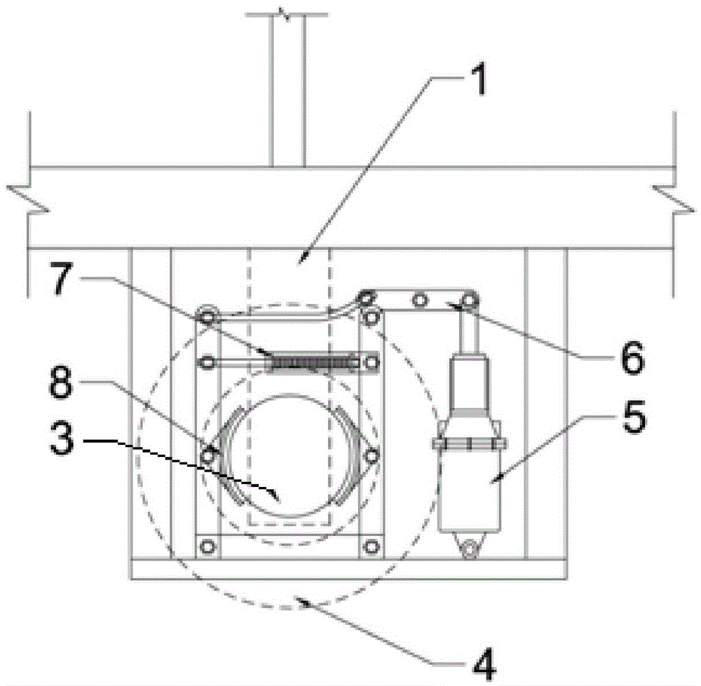
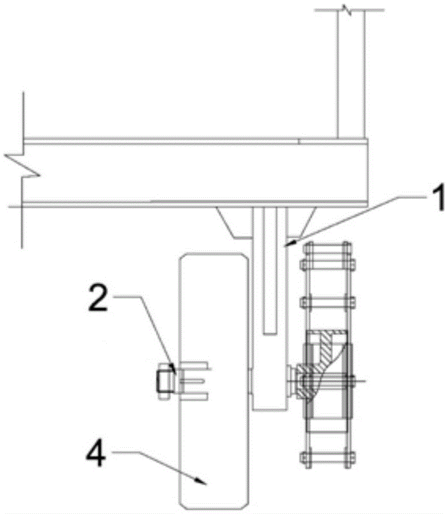
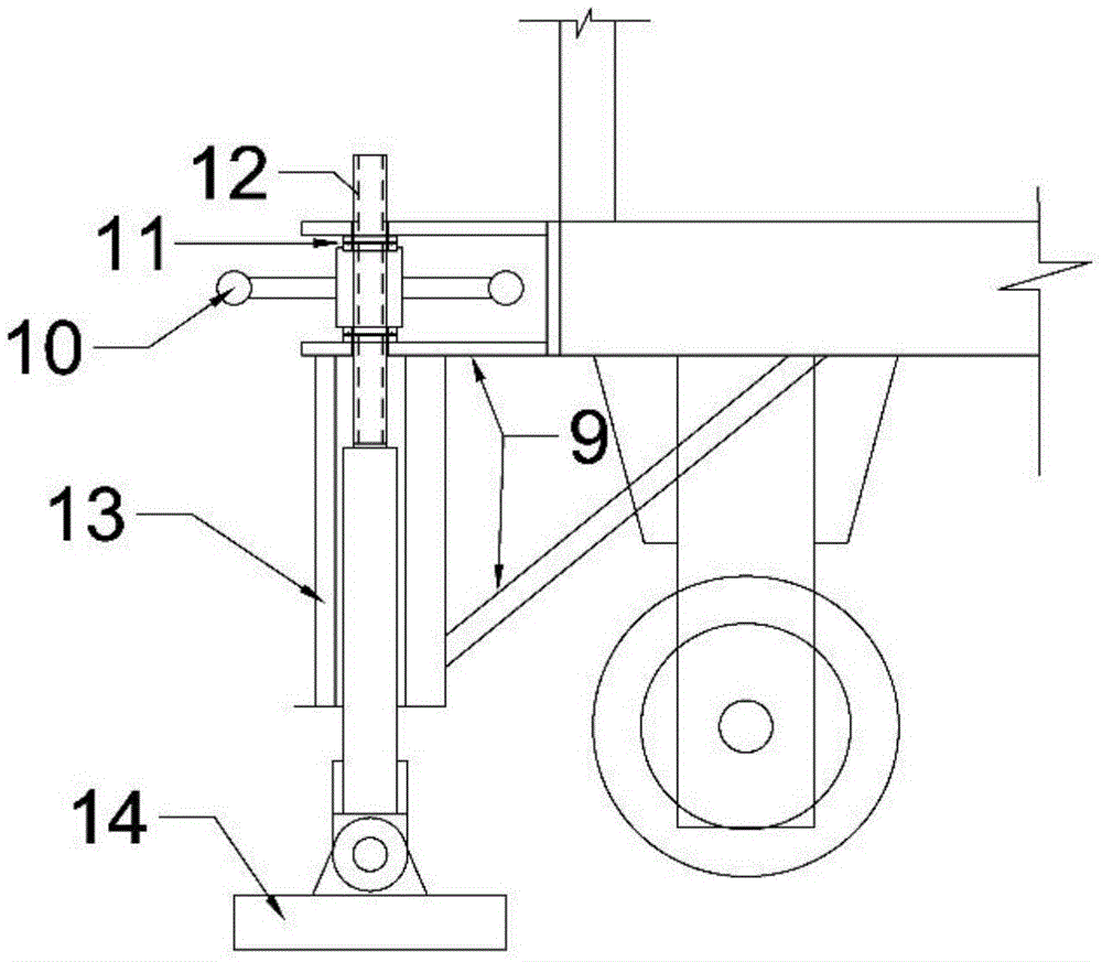
[0033] see Figure 1 to Figure 5 , a braking device for a tunnel grouting trolley, which is composed of a main braking device and an auxiliary braking device. The main braking device includes a tire support 1, an axle 2, a brake wheel 3, a tire 4, an electric hydraulic pump 5, a dowel bar 6, a brake spring 7, and a brake 8. The weight of the upper part of the trolley is transmitted to the tire 4 through the tire bracket 1-axle 2; the brake spring 7 is in a pre-tightened state when the electric hydraulic pump 5 is not working, and the brake 8 at this time holds the brake wheel 3 tightly, and the brake 8 Friction will be generated between the brake wheel 3 and the rotation of the brake wheel 3 will be limited. Since the brake wheel 3 and the tire 4 are connected by the axle 2, when the brake wheel 3 does not rotate, the tire 4 will not be able to rotate , at this mome...


PUM


Abstract

The invention discloses a tunnel grouting trolley braking device and a using method thereof. The tunnel grouting trolley braking device comprises a tire support connected to the lower portion of a grouting trolley, and the two sides of the tire support are connected with a tire and a main braking unit through an axle. The main braking unit comprises a braking wheel fixed to the axle. A hydraulic braking mechanism is arranged on the outer side of the braking wheel and comprises brakes and connecting rods, wherein the brakes are arranged on the two sides of the braking wheel and used for restraining rotation of the braking wheel, and the connecting rods are used for fixing the brakes. A braking spring in a pre-tightened state is connected between the connecting rods. The top ends of the connecting rods are connected with an electric hydraulic pump through a dowel bar, and the electric hydraulic pump can overcome the pre-tightening force of the braking spring. The grouting trolley is further provided with a fixed truss, and the fixed truss is connected with an auxiliary braking unit which generates braking force by rubbing against the ground. The tunnel grouting trolley braking device and the using method thereof can prevent the risk that the grouting trolley slides down due to insufficient braking force when operating on an abrupt slope and consequently casualties and damage to mechanical equipment are caused.

Description

technical field [0001] The invention relates to a grouting technology for a steep slope section of a tunnel, in particular to a braking device for a tunnel grouting trolley and a method for using the same. Background technique [0002] With the development and utilization of underground space by human beings, tunnels (roads) have become an important part of modern transportation, hydropower development, energy mining and other fields. During the construction of traffic tunnels, water diversion tunnels, and coal mine roadways, grouting operations on steep slopes are often encountered. The use of grouting trolleys for grouting operations has good maneuverability and is easy to automate, which can effectively improve grouting efficiency and quality. Therefore, it has been widely used in the construction of tunnels (roads). The mass of the grouting trolley is relatively large. When encountering a steep slope, the braking system of the common grouting trolley cannot meet the req...

Claims


Application Information

Patent Timeline
Patent Type & Authority Applications(China)
IPC IPC(8): B60T1/06B60T1/14
CPCB60T1/06B60T1/14
Inventor 王西奎靳伟强赵武胜严峰桂卫华王川邢秦智刘海张凡孙涛欧亚明杨立双曹相海刘宏宇杜念文
Owner 中国葛洲坝集团第三工程有限公司
Why Eureka
Try Eureka