
A Radiation Area Array Detector and Its Scanning Trace Image Detection System

A detector and radiation surface technology, which is applied in the field of radiation surface array detectors and their scanning line trace image detection systems, can solve the problem of switching cycle, increased coordination difficulty, narrow response band of infrared detectors, and increased target information extraction rate, etc. problem, to simplify the composition and its operation procedures, avoid the precise calibration of the optical axis, and facilitate the screening.

Active Publication Date: 2019-05-03
中国兵器工业第二0五研究所
View PDF7 Cites 0 Cited by
  • Summary
  • Abstract
  • Description
  • Claims
  • Application Information

AI Technical Summary

Problems solved by technology

[0006] Traditional remote sensing and telemetry (microwave radar, photoelectric radar) systems use wavelength (long) intervals and time intervals to develop reconnaissance systems in segments to improve the signal-to-noise ratio of target signals, and use the difference between target infrared sweep images and noise features to increase Target information extraction rate, remote sensing telemetry system based on the above mechanism, (1) the system is huge and complex; (2) corresponding detection systems need to be opened for different reconnaissance environments, the operator's judgment on the reconnaissance environment and the detector switching cycle, The difficulty of coordination is increased; (3) the backscattering of emitted laser light and the electromagnetic radiation of laser power supply interfere with each detection system; (4) the existing infrared detectors have a narrow response band, large pixel size and small number of pixels (compared to CCD detection device comparison)

Method used


Image

  • A Radiation Area Array Detector and Its Scanning Trace Image Detection System
  • A Radiation Area Array Detector and Its Scanning Trace Image Detection System
  • A Radiation Area Array Detector and Its Scanning Trace Image Detection System

Examples


Embodiment 1

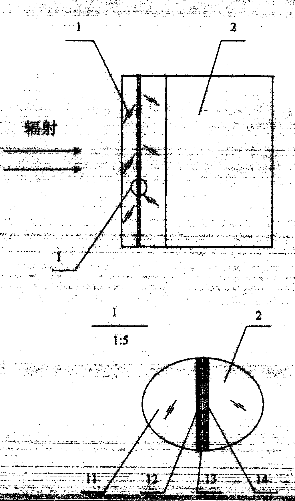
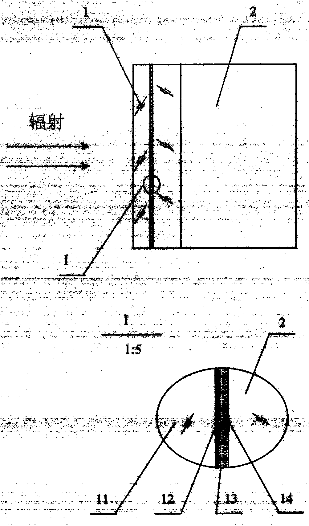
[0021] according to figure 1As shown, the radiation area detector provided in this preferred embodiment includes a radiation conversion sheet 1 and a CCD detector 2, and the radiation conversion sheet 1 is closely attached to the detection surface of the CCD detector 2, and it is characterized in that: the radiation The conversion sheet 1 contains a substrate 11, an array grid 12, an absorbing nanopowder 13, and an upconversion material nanopowder 14. The substrate 1 is a thin optical flat plate through which radiation can pass. In this embodiment, a diamond sheet with a thickness of 100 μm is preferred. The array grid 12 is composed of an array pattern etched from a metal film layer attached to the substrate 11. In this embodiment, a square array grid is formed by photolithography on the gold-plated film layer. The thickness of the gold-plated film layer is 500nm. The interval is 2 μm, and the line width of the grid lines is 250 nm. Each grid through hole of the array grid 12...

Embodiment 2

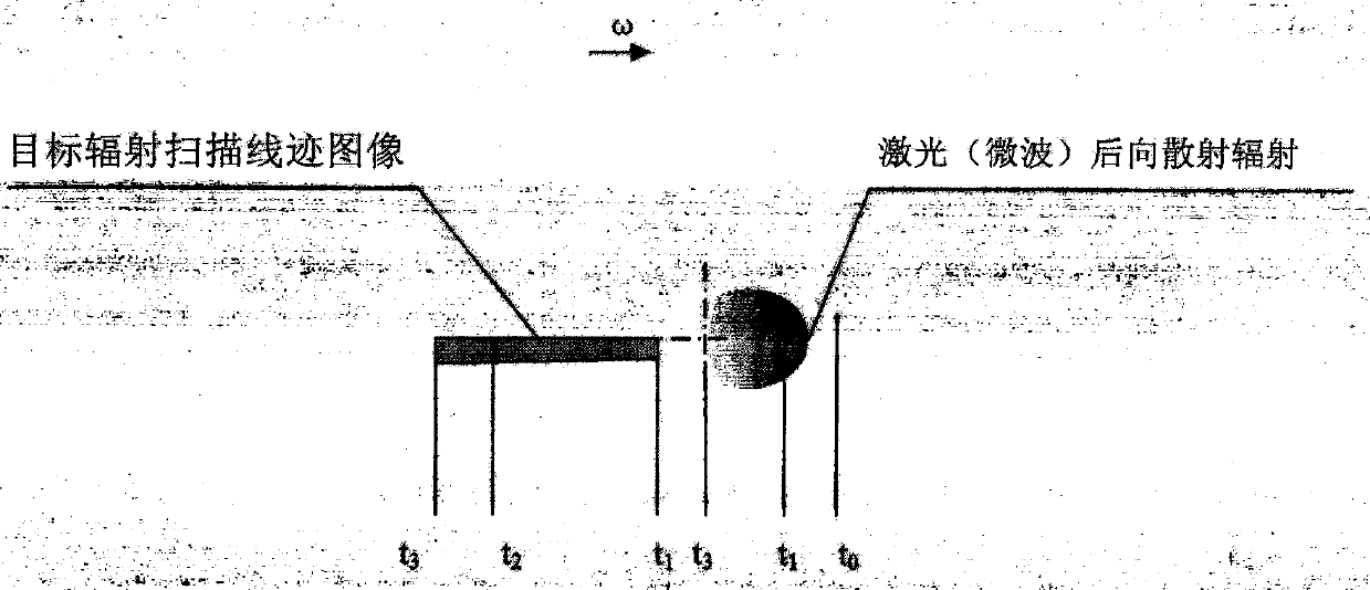
[0023] This preferred embodiment is used in an area monitoring system, including a scanning line trace image detection system using a radiation surface array detector, including a radiation surface array detector, a parabolic mirror, a scanning drive table, a laser (microwave) irradiation system, and a computer scanning line. The trace image processing system is characterized in that: the detection surface of the radiation surface array detector is located on the focal plane of the parabolic mirror, and receives target radiation scanning to form a scanning line trace image; the parabolic mirror is Cassegrain The telescope, the scanning drive table is a rotating platform controlled by a computer to move at a certain angular velocity ω, the radiation area detector and the Cassegrain telescope are fixed on the rotating platform, and the trajectory of the rotating platform is recorded in real time, so that the target radiation The image is scanned on the detection surface of the ra...

Embodiment 3

[0025] This preferred embodiment is used in a radiation detection and guidance system, including a radiation conversion sheet 1, a visible light position-sensitive detector, a telescopic system, a guidance drive assembly, a computer processing and a guidance control system, and is characterized in that: the radiation conversion sheet 1 The array grid 12 is closely attached to the detection surface of the visible light position-sensitive detector. The visible light position-sensitive detector is located on the focal plane of the telescopic system and receives the target radiation image. The visible light position-sensitive detector is a silicon-four-quadrant Detector, the computer processing system collects the four-way current response of the target radiation image on the silicon-four-quadrant detector, takes the difference between the first quadrant and the third quadrant, takes the difference between the second quadrant and the fourth quadrant, and outputs a reverse correction...


PUM

PropertyMeasurementUnit
thicknessaaaaaaaaaa

Abstract

The invention discloses a radiation conversion sheet, a radiation plane array detector and a radiation scanning stitch image detection system of the radiation plane array detector. The radiation conversion sheet is mainly and technical characterized by comprising a substrate, an array grid, absorbing nanometer powder and upper conversion material nanometer powder, wherein a layer of the absorbing nanometer powder and a layer of the upper conversion material nanometer powder are sequentially and uniformly filled on the bottoms of each grid through hole of the array grid so as to form a conversion unit, the radiation conversion sheet absorbs target radiation energy, the radiation wave band is from ultraviolet radiation to far infrared radiation and microwave radiation, the temperature of the absorbing nanometer powder is increased, the emitted infrared radiation is absorbed by the upper conversion material nanometer powder, and visible light is emitted. According to the radiation plane array detector, the array grid of the radiation conversion sheet is closely attached to the detection surface of the visible light detector. The radiation scanning stitch image detection system contains a drive platform for making the radiation image be scanned in the radiation plane array detector. According to the present invention, the characteristic, the direction, the distance and the speed of the target radiation are obtained through the airspace-time domain resolution of the target radiation scanning stitch image.

Description

technical field [0001] The invention belongs to the technical field of remote sensing and telemetry, and mainly relates to a radiation surface array detector based on full-band absorption of radiation by nano-powder and a detection system for radiation scanning trace images thereof, in particular to a thermal radiation based on full-band absorption of nano-powder The detection system of the scanning line image of the area array detector converted into visible light radiation can obtain the target radiation characteristics, orientation, distance and speed by analyzing the space-time domain information of the target radiation image in the scanning line image. Background technique [0002] The infrared image passive reconnaissance system is used in the photoelectric early warning and reconnaissance system. It uses an infrared area array (line array) detector fixed on the turntable. In the scanning image, the signal convolution of the relevant conversion unit that is consistent ...

Claims


Application Information

Patent Timeline
Patent Type & Authority Patents(China)
IPC IPC(8): G01N21/01G01N21/31
Inventor 南瑶贾选军李勤学崔东旭常伟军杨鸿儒
Owner 中国兵器工业第二0五研究所
Learn More