
A network replacement method and control system for a city express rail vehicle control system

A technology of vehicle control system and city area, which is applied in the field of city area fast track vehicle control system network replacement and control system, which can solve the problems of complex vehicle structure and inconvenient operation

Active Publication Date: 2017-06-06
株洲中车轨道交通装备有限公司
View PDF10 Cites 2 Cited by
  • Summary
  • Abstract
  • Description
  • Claims
  • Application Information

AI Technical Summary

Problems solved by technology

[0011] The purpose of the present invention is to use the pantograph of dual power supply system for the existing urban express trains, and two different voltage transformers or sensors are needed to measure and display the catenary voltage behind the pantograph, calculate the electric energy and equipment The control protection function provides a reliable and unique signal, which causes the complexity of the vehicle structure and inconvenient operation. It provides a method of changing the network of the urban fast track control system that can adapt to two different power supply modes of 25kV AC or 1.5kV DC at the same time. And the system device, the system can be completed with only one electronic high-voltage transformer. In the case of two types of catenary, it can provide a reliable and unique system for the catenary voltage measurement display, power calculation and equipment control and protection functions after the pantograph. Signal

Method used


Image

  • A network replacement method and control system for a city express rail vehicle control system
  • A network replacement method and control system for a city express rail vehicle control system
  • A network replacement method and control system for a city express rail vehicle control system

Examples


Embodiment 1

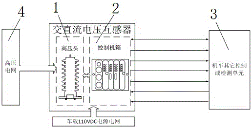
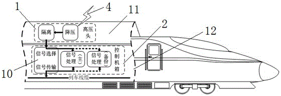
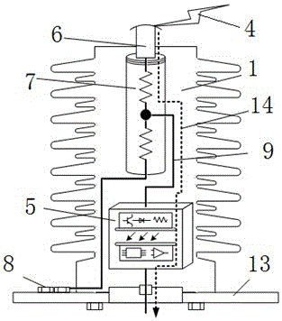
[0041] by attaching Figure 1-4 It can be seen that the present invention relates to a control system for a method of changing nets in an urban fast-track vehicle control system, including a high-voltage head part 1 and a control case part 2, and an AC-DC dual-purpose electronic device formed by combining the high-voltage head part 1 and the control case part 2. type voltage transformer processor; the high-voltage head part 1 includes a high-voltage access terminal 6, a resistor divider 7 and an optical isolator 5; the 25kV AC or 1.5kV DC input from the power grid 4 is first input to the high-voltage access terminal 6, and the high-voltage The access terminal 6 is connected to the top wire of the resistor divider 7, and the outlet wire at the bottom of the resistor divider 7 is connected to the ground terminal 8 of the installation base. There is an outlet wire 9 in the middle of the resistor divider 7, and the outlet wire 9 is for signal sampling Output line: after the resist...

Embodiment 2

[0048] The principle of the second embodiment is the same as that of the first embodiment, except that the high-voltage head of the second embodiment is composed of a high-voltage insulation structure, a voltage divider and an installation structure. The handling of the electrical part is done with voltage dividers and mounting bases. The voltage divider includes a high voltage access terminal, a resistance voltage divider and an optical isolator. The 25kV AC or 1.5kV DC input from the power grid is first input to the high-voltage access terminal, and the high-voltage access terminal is connected to the top wire of the voltage dividing resistor. The bottom outlet of the voltage dividing resistor is connected to the ground terminal of the installation base, and the middle outlet is the signal sampling output wire. After precise resistor division, the high voltage becomes a suitable voltage signal that can be processed by weak electrical appliances. The middle outgoing line of...

Embodiment 3

[0050]The principle of the third embodiment is the same as that of the first embodiment, except that the control cabinet of the third embodiment is divided into a mounting structure, a backplane plug-in, an interface plug-in, a control plug-in and a power plug-in. Among them, the power plug-in and the control plug-in are completely independent and identical. This is because the transformer belongs to the key signal provider of the train. When the transformer breaks down, the relevant operator of the train can toggle the optional switch on the interface plug-in panel to get rid of the faulty system and connect to the normal system. Thereby guaranteeing the normal operation of the train at the fastest speed. Usually, the backup set is in a powerless state to avoid damage caused by abnormal power supply of the locomotive. The voltage signal output from the high-voltage head is connected to the interface plug-in of the control box through the shielded cable; the interface plug-in...


PUM


Abstract

The invention relates to a grid switching method of a control system for inner-city rapid rail vehicles and the control system. An AC (alternating current) or DC (direct current) high voltage signal input by a catenary is directly sent to an AC-DC dual-purpose electronic type voltage transformer after obtained by a pantograph, processed by the AC-DC dual-purpose electronic type voltage transformer and sent to locomotive related equipment in a DC or AC analog manner, and meanwhile, an AC or DC switching value signal is sent to the locomotive related equipment to be used as the unique signal for detecting the voltage system of a power supply grid and the grid voltage value. The control system comprises a high voltage head part and a control case part, wherein the high voltage head part switches 25 kV AC or 1.5 kV DC high voltage from the power supply grid into a proper voltage signal capable of being processed by a weakening device after resistive subdivision; then the control case transmits an input sampling signal to an AC analog output circuit or a DC analog output circuit to be output in an analog manner; the output signal is sent to the locomotive related equipment after amplified and intensified.

Description

technical field [0001] The invention relates to a control method of an electric locomotive and its component device, in particular to a control system of an urban fast track vehicle applicable to both the traction power supply system of a railway electric locomotive and the traction power supply system of an urban rail transit vehicle method and control system. Background technique [0002] With the accelerated development of urbanization in the world, cities are showing a multi-center or radial development trend. At the same time, a large number of satellite cities have risen, prompting a large number of commuting within the city area, outside the central city, and in specific directions (suburban new cities or between the airport and the central city) The emergence of traffic and traffic congestion have become the bottleneck restricting the further development of urbanization. In order to break this predicament, a kind of city area express rail car is released at present ...

Claims


Application Information

Patent Timeline
Patent Type & Authority Patents(China)
IPC IPC(8): B61C3/00B60L5/00
CPCB60L5/00B61C3/00B61C17/00
Inventor 张光群石力乔霄峰
Owner 株洲中车轨道交通装备有限公司
Learn More