Air plasma waste gas treatment device and method
A plasma and waste gas technology, applied in separation methods, chemical instruments and methods, dispersed particle separation, etc., can solve the problems of difficult to deal with high-concentration and large air volume gas, reduced adsorption effect, difficult cleaning and replacement, etc., and achieve efficient decomposition. The effect of processing energy consumption, high exhaust gas treatment efficiency, and easy disassembly and cleaning
Inactive Publication Date: 2015-06-10
SUZHOU UNIV
View PDF3 Cites 6 Cited by
- Summary
- Abstract
- Description
- Claims
- Application Information
AI Technical Summary
Problems solved by technology
(2) For VOCs with medium and low concentrations, although the adsorption method is more effective and simple, the VOCs that can react with activated carbon are not suitable for recovery and treatment by this method; in addition, the adsorption effect of the adsorbent decreases after repeated regeneration, and it needs to be replaced regularly ; Adsorption also produces secondary solid or liquid pollutants
Factors affecting the treatment effect of the system include operating temperature, gas-liquid contact area, liquid-gas ratio, etc. Lowering the operating temperature, increasing the liquid-gas contact surface, and increasing the liquid-gas ratio will increase the absorption efficiency, but the system resistance and energy consumption will also increase accordingly
(4) The biological treatment technology of VOCs gas includes biological filtration, biological trickling, biological washing, activated sludge and membrane biological method, etc. This method is suitable for low concentration and large flow gas, but its biodegradation rate is limited , the load cannot be too high, and the treatment effect on biologically toxic substances is poor
(5) Photocatalytic oxidation method: When light is irradiated on the semiconductor catalyst, the generated holes have a strong ability to obtain electrons, which can be combined with OH and H on the surface 2 O, etc. react to generate hydroxyl radicals (OH·) with strong oxidizing ability, OH· can oxidize almost all organic matter and make it mineralized, but there are still some defects, such as the reaction is limited by ultraviolet light source; the energy yield is low ; Difficult to handle high-concentration, high-volume gases, etc.
However, the existing DBD plasma waste gas treatment system has a series of shortcomings as follows: (1) Its discharge mainly adopts a tubular dielectric structure, and the electrodes are located in the tube cavity. The inner wall of the tubular dielectric barrier layer is easy to be polluted during waste gas treatment, Difficult to clean and replace; (2) The volume of the plasma treatment area is relatively small; (3) After the tubular dielectric barrier material is contaminated, it will cause uneven thermal expansion due to uneven heat dissipation, which will cause unsafe factors such as bursting of the dielectric tube; (4) ) Poor compatibility with other existing exhaust gas treatment systems
Method used
View moreImage
Smart ImageViewing Examples
Examples
Embodiment 1
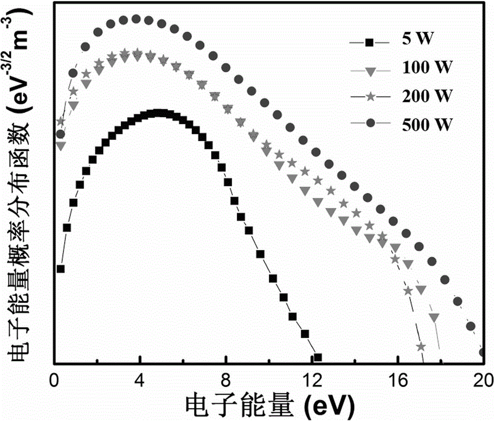
[0037]Example 1: Air flow rate 1slm, output power 5W.
Embodiment 2
[0038] Example 2: Air flow rate 25slm, output power 100W.
Embodiment 3
[0039] Example 3: Air flow rate 50slm, output power 200W.
Login to View More PUM
 Abstract
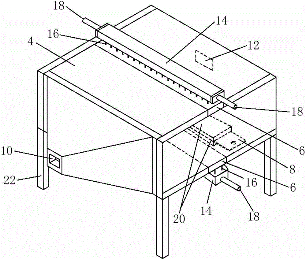
The invention relates to an air plasma waste gas treatment device. The air plasma waste gas treatment device comprises a high-voltage alternating-current power supply, a housing, two first dielectric slabs installed on the housing and a grounding electrode arranged in the housing, wherein a waste gas inlet and a waste gas outlet are respectively formed in two ends of the housing, a high-voltage electrode is installed on each first dielectric slab and comprises a conductive tube and a capillary tube with one end extending into the conductive tube, an air inlet is formed in at least one end of the conductive tube, the conductive tube is connected with the high-voltage end of the high-voltage alternating-current power supply, the grounding electrode is connected with the grounding end of the high-voltage alternating-current power supply, and the other end of the capillary tube is communicated with the housing. The invention further relates to an air plasma waste gas treatment method. The air plasma waste gas treatment device and method have the advantages of efficient decomposition and low treatment power consumption, and a new thought is provided for industrial waste gas treatment.
Description
technical field [0001] The invention relates to an air plasma treatment device and method for waste gas. Background technique [0002] With the rapid development of the economy, the volatile organic waste gases (VOCs) produced by industries such as petroleum, pharmaceuticals, paints, printing and coatings are increasing day by day. These waste gases entering the atmosphere will bring serious pollution to the environment and have a great impact on human health. Harm, causing huge losses to the national economy. In recent years, the state has promulgated the "Comprehensive Work Plan for Energy Conservation and Emission Reduction" and the "Eleventh Five-Year Plan" for the Prevention and Control of Acid Rain and Sulfur Dioxide Pollution, and adopted "preferential electricity prices for desulfurization", "reducing the large and reducing the small", and "eliminating within a limited time" A series of policies and measures such as "Regional Approval Restrictions", increase investm...
Claims
Login to View More Application Information
Patent Timeline
 IPC IPC(8): B01D53/32
Inventor 金成刚吴磊王心韵田润杨东谨胡一波诸葛兰剑吴雪梅
Owner SUZHOU UNIV
Features
- R&D
- Intellectual Property
- Life Sciences
- Materials
- Tech Scout
- Unparalleled Data Quality
- Higher Quality Content
- 60% Fewer Hallucinations
Learn More Browse by: Latest US Patents, China's latest patents, Technical Efficacy Thesaurus, Application Domain, Technology Topic, Popular Technical Reports.
© 2025 PatSnap. All rights reserved.Legal|Privacy policy|Modern Slavery Act Transparency Statement|Sitemap|About US| Contact US: help@patsnap.com


