
Ladle preheating kiln

A kiln and ladle technology, which is applied to casting melt containers, metal processing equipment, casting equipment, etc., can solve the problems of heavy cost burden, low utilization rate of gas combustion heat, and high energy consumption, so as to reduce gas consumption, Good heat storage effect and uniform heat absorption effect

Inactive Publication Date: 2015-05-20
马斌
View PDF0 Cites 2 Cited by
  • Summary
  • Abstract
  • Description
  • Claims
  • Application Information

AI Technical Summary

Problems solved by technology

The existing ladle baking process is to directly use the burner to bake the ladle one by one. The baking process consumes a lot of energy. The gas consumption of each ladle during the baking process is about 1500Nm 3 / H, the cost burden of the enterprise is heavy
When the existing ladle baking equipment bakes the ladle, it is necessary to reserve a certain space at the lid of the ladle for exhaust gas, otherwise the new heat source cannot enter the ladle, and a large amount of heat rises with the exhaust gas during the process of exhaust gas. Exhaust, the heat utilization rate of gas combustion is low

Method used


Image

  • Ladle preheating kiln
  • Ladle preheating kiln

Examples


Embodiment Construction

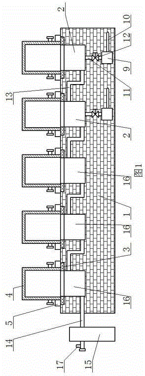
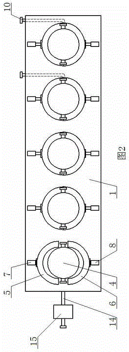
[0008] The ladle baking kiln of the present invention comprises a kiln base 1, at least one direct-heating furnace mouth 2 and at least one waste heat furnace mouth 16 are arranged on the top surface of the kiln base 1, each direct-heating furnace mouth 2 and each waste heat furnace The mouths 16 are connected in turn through the flue gas passage 13. The direct heating furnace mouth 2 is located on the side of the inlet end of the flue gas passage 13, and the waste heat furnace mouth 16 is located on the side of the outlet end of the flue gas passage 13. The heat pipe 11 communicates with the burner 9, the burner 9 communicates with the intake pipe 10, and a waste heat furnace mouth 16 near the outlet end of the flue gas channel 13 communicates with the waste gas pipe 14, and the induced draft fan 15 is installed on the waste gas pipe 14. When baking the ladle, put the ladle 4 upside down above the direct heating furnace mouth 2 and the waste heat furnace mouth 16, and the ladl...


PUM


Abstract

The invention provides a ladle preheating kiln which comprises a kiln base. At least one direct-heating kiln opening and at least one waste heat kiln opening are formed in the top face of the kiln base. The direct-heating kiln openings and the waste heat kiln openings are sequentially communicated through a smoke channel respectively. The direct-heating kiln openings are located in one side of the gas inlet end of the smoke channel. The waste heat kiln openings are located in one side of the gas outlet end of the smoke channel. The direct-heating kiln openings are communicated with a combustion engine through heat supply pipes. The combustion engine is communicated with a gas inlet pipe. The waste heat kiln opening close to the gas outlet end of the smoke channel is communicated with a waste gas pipe which is provided with an induced draft fan. A stop valve is installed on each heat supply pipe. By means of the ladle preheating kiln, the gas consumed for baking ladles can be effectively reduced for iron and steel enterprises, and meanwhile the gas combustion heat utilization rate is greatly increased.

Description

technical field [0001] The invention relates to a ladle heating device, in particular to a ladle baking kiln. Background technique [0002] Ladle baking is a very important process in steel production. The baking process seriously affects the energy consumption of enterprises and the quality of products. The existing ladle baking process is to directly use the burner to bake the ladle one-to-one, the energy consumption of the baking process is high, and the gas consumption of each ladle during the baking process is about 1500Nm 3 / H, the cost burden of the enterprise is heavy. When the existing ladle baking equipment bakes the ladle, it is necessary to reserve a certain space at the lid of the ladle for exhaust gas, otherwise the new heat source cannot enter the ladle, and a large amount of heat rises with the exhaust gas during the process of exhaust gas. Exhaust, the heat utilization rate of the gas after combustion is low. Contents of the invention [0003] The purp...

Claims


Application Information

Patent Timeline
Patent Type & Authority Applications(China)
IPC IPC(8): B22D41/015
CPCB22D41/015
Inventor 马斌
Owner 马斌
Learn More