
Complete-machine static rigidity detection control system for numerical control machine tool

A technology of detection control system and numerical control machine tool, which is applied in the field of numerical control machine tool, can solve the problems of no test system or instrument device, scattered test system, and inability to apply in large quantities, so as to improve detection efficiency and precision, realize automation and diversify functions Effect

Inactive Publication Date: 2015-03-25
鼎奇(天津)主轴科技有限公司
View PDF9 Cites 6 Cited by
  • Summary
  • Abstract
  • Description
  • Claims
  • Application Information

AI Technical Summary

Problems solved by technology

Although there have been many literatures published on the static stiffness test methods of machining centers, there is not a very mature, simple, and universally applicable test method, and there is no reliable test system or instrument device to meet the current production requirements. Due to the large demand of enterprises and universities, the research of a large number of scholars only stays in the scheme or experiment. Most of the developed test methods can only measure the static stiffness in a certain direction, instead of measuring the three directions of x, y and z at the same time. big limitations
And even if the static stiffness in three directions can be measured, the test system is too fragmented to be widely used. The advanced static stiffness detection and control system of the CNC machine tool developed by the present invention can realize the static stiffness of the structure in a single direction or multiple vertical directions. The test and research results are suitable for universities and machine tool manufacturers, and are of great significance to make up for the lack of static stiffness measurement devices in the current CNC machine tool industry.

Method used


Image

  • Complete-machine static rigidity detection control system for numerical control machine tool
  • Complete-machine static rigidity detection control system for numerical control machine tool
  • Complete-machine static rigidity detection control system for numerical control machine tool

Examples


Embodiment Construction

[0015] In order to further understand the invention content, characteristics and effects of the present invention, the following examples are given, and detailed descriptions are as follows in conjunction with the accompanying drawings:

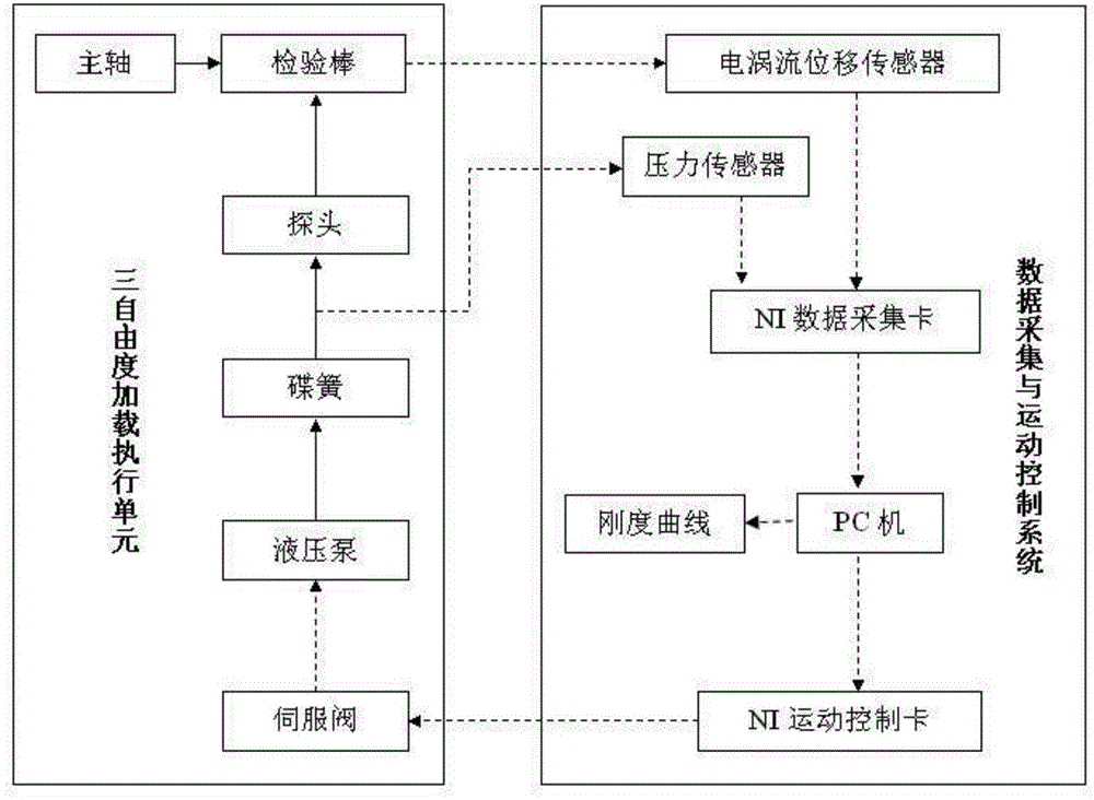
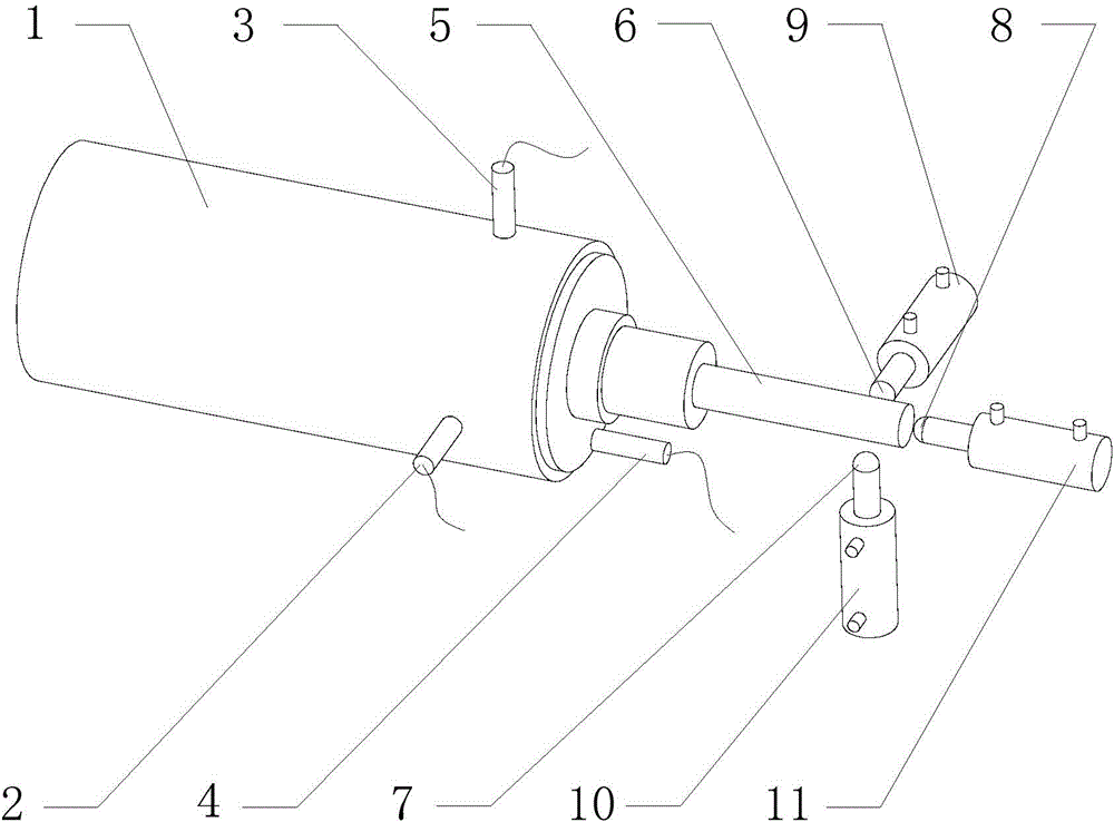
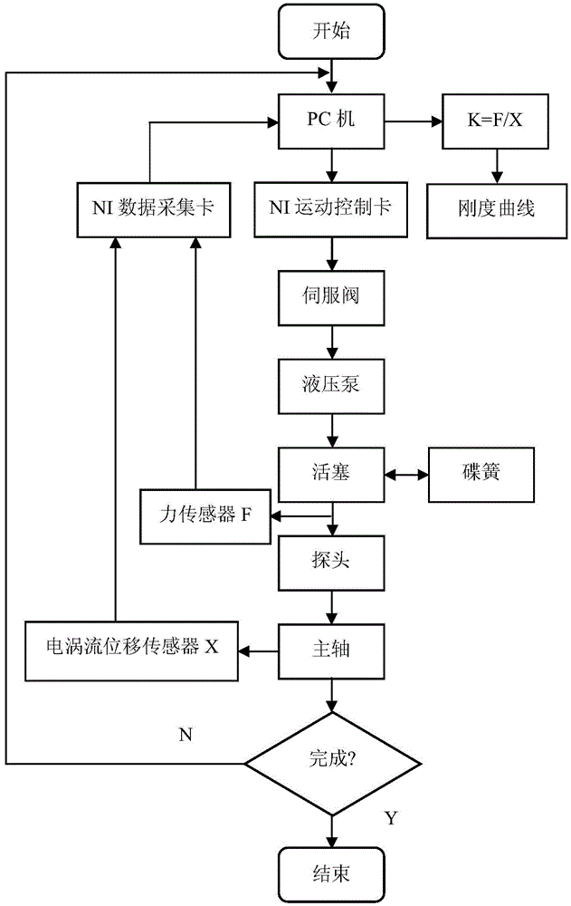
[0016] See figure 1 , figure 2 and image 3 , the present invention is used in the static stiffness detection and control system of CNC machine tools, mainly composed of a data acquisition system, a motion control system and a three-degree-of-freedom loading execution unit; the three-degree-of-freedom loading execution unit is mainly composed of the data acquisition system and the control The system consists of pressure sensor, eddy current displacement sensor 2, 3 and 4, NI data acquisition system card, NI motion control card and PC. The three-degree-of-freedom loading execution unit is mainly composed of servo valves, hydraulic cylinders 9, 10 and 11, disc springs, probes and a test rod installed on the main shaft 1.

[0017] There is a...


PUM


Abstract

The invention discloses a complete-machine static rigidity detection control system for a numerical control machine tool. The complete-machine static rigidity detection control system is mainly composed of a data collecting and movement control system and a three-degree-of-freedom loading executing unit. The data collecting and movement control system is composed of a force sensor, an eddy current displacement sensor, an NI data collecting card, an NI movement control card and a PC. The three-degree-of-freedom loading executing unit is mainly composed of a servo valve, a hydraulic cylinder, a disc spring, a probe and a check rod installed on a main shaft. According to the complete-machine static rigidity detection control system, the loading force is controlled by the computer, signal processing is detected through the sensors, automation of a detection system is achieved to a certain degree, and the complete-machine static rigidity detection control system is reliable and convenient to operate and can be widely applied.

Description

technical field [0001] The patent of the present invention relates to a performance detection system in the field of numerically controlled machine tools, in particular to a static stiffness detection and control system of a complete numerically controlled machine tool. Background technique [0002] The static stiffness of the CNC machine tool refers to its ability to resist deformation when it bears a constant load in three vertical directions in space. It is an important indicator of machine tool design. The static performance of the machine tool will affect its dynamic characteristics. The static deformation of the machine tool under the action of the machine tool will not only change the geometric accuracy of the parts and reduce the processing quality, but also affect the vibration resistance, productivity, noise, working life, motion balance, heat generation and wear of the machine tool. , in order to accurately and reliably design the spindle and other parts of the CN...

Claims


Application Information

Patent Timeline
Patent Type & Authority Applications(China)
IPC IPC(8): G01M13/00
Inventor 吕术亮国冬张莹
Owner 鼎奇(天津)主轴科技有限公司
Learn More