
Heat Exchanger

A heat exchanger and heat exchange tube technology, which is used in the fields of HVAC, refrigeration, transportation, and automobiles, can solve the problems of uneven distribution of two-phase refrigerants, save time and resources, increase heat exchange area, and increase The effect of heat transfer performance

Active Publication Date: 2017-02-22
DANFOSS MICRO CHANNEL HEAT EXCHANGER JIAXING
View PDF3 Cites 0 Cited by
  • Summary
  • Abstract
  • Description
  • Claims
  • Application Information

AI Technical Summary

Problems solved by technology

[0007] One of the purposes of the present invention is to solve the problem of uneven distribution of two-phase refrigerant in heat exchangers such as microchannel heat exchangers

Method used


Image

  • Heat Exchanger
  • Heat Exchanger
  • Heat Exchanger

Examples


Embodiment Construction

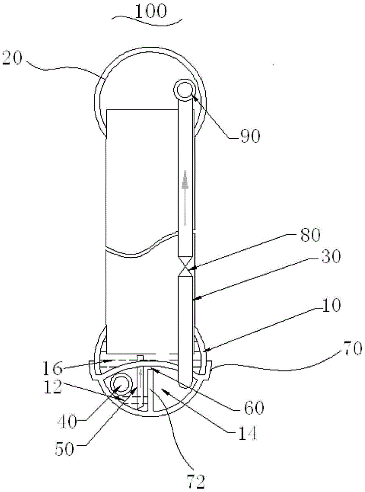
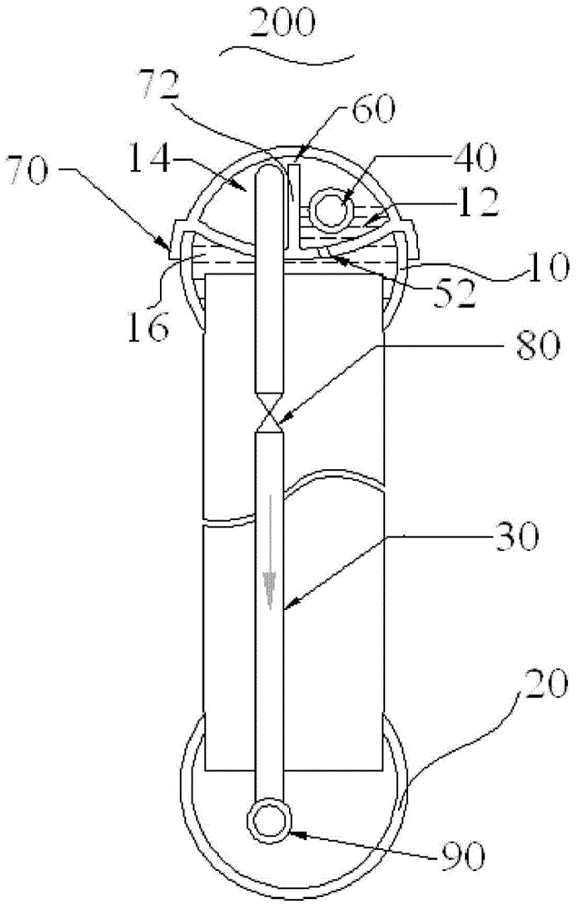
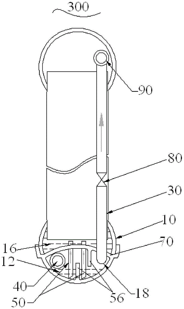
[0040] Through the following examples, combined with the attached Figure 1-6 , the technical solution of the present invention will be further specifically described. In the specification, the same or similar reference numerals designate the same or similar components. The following description of the embodiments of the present invention with reference to the accompanying drawings is intended to explain the general inventive concept of the present invention, but should not be construed as a limitation of the present invention.

[0041] see figure 1, shows a side partial cross-sectional view of a heat exchanger 100 according to a first embodiment of the present invention. The heat exchanger 100 includes an inlet header 10 located at the lower part of the heat exchanger 100, an outlet header 20 located at the upper part of the heat exchanger 100, and at least one valve connected between the inlet header 10 and the outlet header 20. One or more heat exchange tubes (not shown)...


PUM


Abstract

A heat exchanger (100) comprises an inlet collecting pipe (10), an outlet collecting pipe (20) and a heat exchange pipe and a gas pipe (30) connected between said inlet and outlet connecting pipes (10, 20). The inlet collecting pipe (10) comprises at least two separate chambers, a two-phase refrigerant chamber (12) for containing gas- or liquid-phase refrigerant entering the inlet collecting pipe (10), and a liquid refrigerant chamber (16) for containing liquid-phase refrigerant after separation. Gas- or liquid-phase refrigerant entering the inlet collecting pipe (10) is first contained within the two-phase refrigerant chamber (12), then, after separation, liquid-phase refrigerant enters the liquid refrigerant chamber (16), then enters the heat exchange pipe for heat exchange; after heat exchange, the refrigerant enters the outlet collecting pipe (20). Gas-phase refrigerant flows to the outlet collecting pipe (20) through the gas pipe (30).

Description

technical field [0001] The invention relates to the fields of HVAC, automobiles, refrigeration and transportation, in particular to heat exchangers such as microchannel evaporators, parallel flow evaporators and heat pumps. Background technique [0002] At present, finned copper tube heat exchangers are still the main air conditioner heat exchangers on the market, but finned copper tube heat exchangers have problems such as high cost, poor electrical corrosion resistance, and complicated welding processes. [0003] When the heat exchanger is used as an evaporator, the refrigerant entering the heat exchanger is a two-phase refrigerant or refrigerant. In particular, whether the liquid refrigerant can be evenly distributed to each channel or heat exchange tube for heat exchange is a key issue. The design of this type of heat exchanger is critical. At present, microchannel heat exchangers generally have the problem of uneven distribution of two-phase refrigerant, which leads to...

Claims


Application Information

Patent Timeline
Patent Type & Authority Patents(China)
IPC IPC(8): F25B39/02
CPCF25B39/02F25B43/00F25B2400/23F25B2500/18F28D1/05366F28D2021/0085F28F9/0204F28F9/026
Inventor 蒋建龙徐阳
Owner DANFOSS MICRO CHANNEL HEAT EXCHANGER JIAXING
Learn More