Long screw rod fastening guide wear-resistant sleeve reciprocating impact excavating part easy to machine as well as assemble and disassemble for mining machine
A wear-resistant sleeve and long screw technology, applied in the mechanical field, can solve problems such as increased material costs, high processing difficulty, and equipment failure, and achieve the effects of improving accuracy, improving processing accuracy and performance, and reducing difficulty
- Summary
- Abstract
- Description
- Claims
- Application Information
AI Technical Summary
Problems solved by technology
Method used
Image
Examples
Embodiment 1
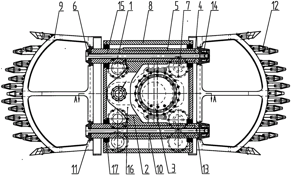
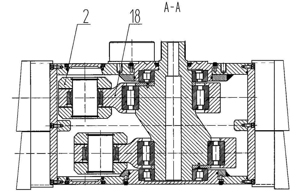
[0082] figure 1 and figure 2 It is a mining machine described in Example 1, which is fastened with a long screw and is easy to process and disassemble. Sleeve 4, wear-resistant sleeve positioning mechanism 5, guide screw fastening mechanism 6, rolling friction body 7, box body 8 and impact head 9, etc., one or both ends of the impact guide 1 protrude outside the box body 8, and the impact guide 1 includes a guide core rod 10, etc., the guide wear-resistant sleeve 4 is arranged on the guide core rod 10, the guide wear-resistant sleeve 4 is arranged between the impact guide 1 and the box body 8 and / or is arranged between the impact guide 1 and the rolling friction Between the body 7, the guide wear-resistant sleeve 4 is positioned by the wear-resistant sleeve positioning mechanism 5, the guide rod connector 2 is connected with the impact guide 1 in the box body 8, and the impact guide 1 is separately connected with the guide rod connector 2, The impact head 9 is arranged on o...
Embodiment 2
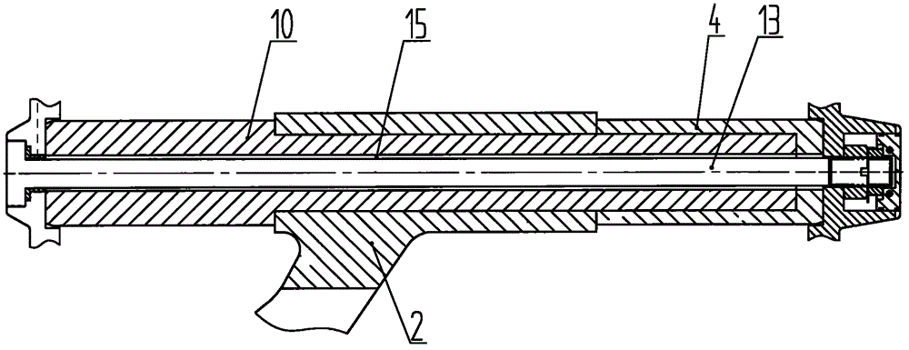
[0086] image 3 and Figure 4 It is a mining machine described in Example 2, which is fastened with a long screw and is easy to process, disassemble, guide and wear-resistant sleeve to reciprocate and impact the mining part. The difference from Embodiment 1 is that the guide rod connector 2 is separated from the guide core rod 10, and when the guide rod connector 2 and the guide rod 10 are separated, the guide rod connector 2 is provided with a hole through the guide rod , the guide mandrel 10 passes through the guide mandrel hole, and the guide wear-resistant sleeve 4 is set at one or both ends of the guide mandrel 10, the guide mandrel 10 is separated from the guide screw 13, when the guide mandrel 10 and the guide screw 13 are separated The guide core rod 10 is provided with a hole 15 through which the guide screw rod is inserted.
[0087] It is also possible to make one end of the guide core rod 10 and the guide wear-resistant sleeve 4 an integral structure, the other en...
Embodiment 3
[0093] Figure 5 It is a excavator described in Example 3, which is fastened with a long screw and is easy to process, disassemble, guide and wear-resistant sleeve to reciprocate and impact the excavation part. The difference from Embodiment 1 is that the wear-resistant sleeve positioning mechanism 5 includes an interference positioning mechanism, a cone positioning mechanism, a shoulder positioning mechanism, a pin shaft positioning mechanism, a thread positioning mechanism, a circlip positioning mechanism or a retaining sleeve positioning mechanism. Mechanism or clamp positioning mechanism or buckle groove positioning mechanism or block positioning mechanism 59 or expansion pin positioning mechanism, etc., impact guide 1 includes guide core rod 10 and / or impact guide rod, etc., block positioning mechanism 59 includes impact guide Rod stop platform 24 or lead screw stop platform 25 or guide rod connector stop platform 63 or punch tooth seat stop platform 60 or wear-resistant ...
PUM
 Abstract
Description
Claims
Application Information
 - R&D
- Intellectual Property
- Life Sciences
- Materials
- Tech Scout
- Unparalleled Data Quality
- Higher Quality Content
- 60% Fewer Hallucinations
Browse by: Latest US Patents, China's latest patents, Technical Efficacy Thesaurus, Application Domain, Technology Topic, Popular Technical Reports.
© 2025 PatSnap. All rights reserved.Legal|Privacy policy|Modern Slavery Act Transparency Statement|Sitemap|About US| Contact US: help@patsnap.com


