Method for controlling growth of carbon nanotube bundle in horizontal direction of substrate

A carbon nanotube bundle, horizontal direction technology, applied in nanotechnology, nanotechnology, nanostructure manufacturing and other directions, can solve problems such as inability to meet nanoelectronic devices, complex template processing, damage to carbon nanotube structures, etc., and achieve precise and controllable positions. , the process is simple, the effect of easy integration

Inactive Publication Date: 2015-03-11
WUHAN UNIV
View PDF7 Cites 0 Cited by
  • Summary
  • Abstract
  • Description
  • Claims
  • Application Information

AI Technical Summary

Problems solved by technology

However, this method mainly has the following defects: First, the controllability of the through-hole template preparation in the horizontal direction is poor. Although the through-hole density on the template can be controlled at present, the aperture size and the arrangement of the through-holes cannot be precisely controlled; the second is It is very difficult to prepare through-hole templates in the horizontal direction and the post-template processing is more complicated
Although these post-synthesis alignment methods can remove impurities such as catalysts in advance, the alignment conditions are mild, and it is easy to produce large-scale, highly oriented carbon nanotube bundles, but the structure of carbon nanotubes and the introduction of carbon nanotube bundles are bound to be destroyed when dispersed. impurities, and these methods cannot precisely control the position and size of carbon nanotube bundles
[0004] To sum up, the existing technology cannot realize carbon nanotube bundles with precise and controllable size and position in the horizontal direction of the substrate, which cannot meet the needs of most nanoelectronic devices.

Method used


Image

  • Method for controlling growth of carbon nanotube bundle in horizontal direction of substrate
  • Method for controlling growth of carbon nanotube bundle in horizontal direction of substrate

Examples


Embodiment 1

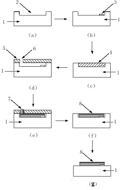
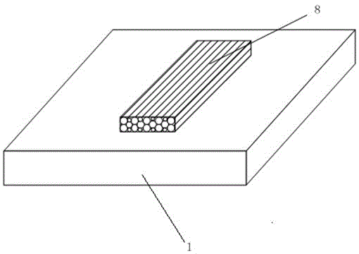
[0043] (1) Prepare a piece of silicon wafer 1, use conventional semiconductor cleaning process to clean, dry, use photolithography process and ion reactive etching process to process a 10 micron long and 2 wide carbon nanotube film on the surface of the silicon wafer Micron, horizontal micro-nano channel 2 with a depth of 2 microns;

[0044] (2) Spin-coat a layer of AZ4620 photoresist on the surface of the silicon wafer 1 with a coater, with a thickness of 3 microns, expose and develop the catalytic film deposition window, and deposit 6 nm-thick photoresist on the surface of the silicon wafer sequentially using an electron beam evaporation process. The Al2O3 layer and the 1 nanometer thick Co layer form the catalytic film 3, the photoresist is removed, and the catalytic film on the photoresist is removed together thereupon, leaving the patterned catalytic film 3 in the micro-nano channel 2, the catalysis The film size is 2 microns wide and 2.2 microns long;

[0045] (3) Spin-...

Embodiment 2

[0050] (1) Prepare a piece of quartz plate 1, use conventional semiconductor cleaning process to clean, dry, use photolithography process and ion reaction etching process to process 10 microns in length and 2 microns in width at the position where carbon nanotube bundles need to be grown on the surface of the quartz plate , a horizontal micro-nano channel 2 with a depth of 2 microns;

[0051] (2) Spin-coat a layer of AZ4620 photoresist on the surface of the quartz plate 1 with a homogenizer, with a thickness of 3 microns, expose and develop the catalytic film deposition window, and deposit 10 nanometers of photoresist on the surface of the quartz plate sequentially using an electron beam evaporation process. The Al2O3 layer and the 2 nanometer thick Fe layer form the catalytic film 3, remove the photoresist, and the catalytic film on the photoresist is removed together thereupon, leaving the patterned catalytic film 3 in the micro-nano channel 2, catalyzed The membrane size is...

Embodiment 3

[0057] (1) Prepare a piece of aluminum oxide sheet 1, clean it with conventional semiconductor cleaning process, dry it, and use photolithography process and ion reaction etching process to process a 10 micron long and 2 wide carbon nanotube bundle on the aluminum oxide surface. Micron, horizontal micro-nano channel 2 with a depth of 2 microns;

[0058] (2) Spin-coat a layer of AZ4620 photoresist on the surface of alumina sheet 1 with a coater, with a thickness of 3 microns, expose the catalytic film deposition window by exposure and development, and deposit 12 nanometers on the surface of alumina sheet sequentially using electron beam evaporation process A thick Al2O3 layer and a 3nm-thick Ni layer form the catalytic film 3, the photoresist is removed, and the catalytic film on the photoresist is removed together, leaving the patterned catalytic film 3 in the micro-nano channel 2 , the size of the catalytic membrane is 2.4 microns in length and 2 microns in width;

[0059] (...


PUM

PropertyMeasurementUnit
thicknessaaaaaaaaaa
thicknessaaaaaaaaaa
thicknessaaaaaaaaaa

Abstract

The invention discloses a method for controlling the growth of a carbon nanotube bundle in the horizontal direction of a substrate, and belongs to the technical field of nanomaterial preparation. The method comprising the following steps: (1) processing a micro-nano channel on the surface of a substrate in the horizontal direction; (2) depositing a catalyst film at one end of the bottom of the micro-nano channel and then patterning the catalyst film; (3) depositing an all-sacrificial layer; (4) depositing a masking layer, and etching an air hole communicated with the micro-nano channel on the masking layer at the top at the other end at the bottom of the micro-nano channel, removing the sacrificial layer to form a semi-closed micro-nano channel; (5) growing a carbon nanotube bundle in the semi-closed micro-nano channel; (6) removing the masking layer, the carbon nano tube in the air hole and the substrate around the carbon nanotube bundle to obtain a carbon nanotube bundle with the same size as the micro-nano channel in the horizontal direction of the substrate. The method provided by the invention has the advantages that a carbon nanotube bundle with precisely controlled orientation, size and location can be obtained in the horizontal direction of the substrate; the process is simple and easy to implement, and can be extensively used.

Description

technical field [0001] The invention relates to a method for controllably growing carbon nanotube bundles in the horizontal direction of a substrate, and belongs to the technical field of nanomaterial preparation. Background technique [0002] Carbon nanotubes are seamless, hollow tubes formed by curling graphene sheets formed by carbon atoms, with a diameter of several nanometers to tens of nanometers and a length of more than tens of microns. As a unique one-dimensional nanomaterial, carbon nanotubes have excellent mechanical properties, outstanding electrical properties and stable chemical properties. Materials, hydrogen storage materials and many other fields have shown broad application prospects. In the above-mentioned many application fields, especially in the field of nanoelectronic devices, it is an important prerequisite to realize the practical application of carbon nanotubes to grow carbon nanotube bundles with an ordered array structure in the horizontal direct...

Claims


Application Information

Patent Timeline
Patent Type & Authority Applications(China)
IPC IPC(8): B81C1/00B82B3/00B82Y40/00
Inventor 刘锋刘胜王国平蔡华飞
Owner WUHAN UNIV
Why Eureka
Try Eureka