
Casting device

A mold and support surface technology, applied in casting equipment, equipment for feeding molten metal into casting molds, metal processing equipment, etc., can solve the problems of unfavorable casting mold cooling, cumbersome casting process, slow cooling process, etc., to save casting Time, convenient demoulding process, good fixation effect

Inactive Publication Date: 2015-03-04
耒阳市诚松有色金属再生有限公司
View PDF1 Cites 0 Cited by
  • Summary
  • Abstract
  • Description
  • Claims
  • Application Information

AI Technical Summary

Problems solved by technology

This invention solves the technical problems of cumbersome casting process, slow cooling process and low work efficiency in the prior art, but this invention only facilitates the cooling of a single casting mold, which is not conducive to the simultaneous cooling of a large number of casting molds

Method used


Image

  • Casting device
  • Casting device
  • Casting device

Examples


specific Embodiment 1

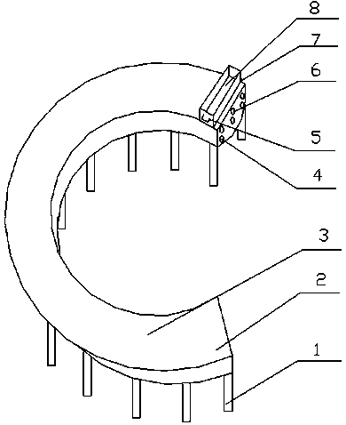
[0019] as attached figure 1 As shown, a casting device includes a casting mold 8 and a bracket 3. The casting mold 8 is placed on the bracket 3. The bracket 3 is an open curved structure. The bracket 3 is welded by the support rod 1 at the lower end and the support surface 2 at the upper end. , the upper surface of the supporting surface 2 is a horizontal structure, a row of water inlet pipes 6 and a water outlet pipe 4 are arranged in the supporting surface 2, the water inlet pipes 6 are above the water outlet pipes 4, and the bottom surface of the casting mold 8 is in complete contact with the supporting surface 2, The tangent at the point of contact between the casting mold 8 and the support surface 2 is perpendicular to the length direction of the casting mold 8, and the bottom surface of one end of the casting mold 8 in the length direction is connected to the side with a larger curvature radius on the support surface 2 in a rotatable manner, and the casting mold 8. The o...

specific Embodiment 2

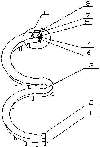
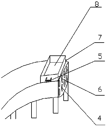
[0024] as attached figure 2 And attached image 3 As shown, a casting device includes a casting mold 8 and a bracket 3. The casting mold 8 is placed on the bracket 3. The bracket 3 is an open curved structure. The bracket 3 is welded by the support rod 1 at the lower end and the support surface 2 at the upper end. , the upper surface of the supporting surface 2 is a horizontal structure, a row of water inlet pipes 6 and a water outlet pipe 4 are arranged in the supporting surface 2, the water inlet pipes 6 are above the water outlet pipes 4, and the bottom surface of the casting mold 8 is in complete contact with the supporting surface 2, The tangent at the point of contact between the casting mold 8 and the support surface 2 is perpendicular to the length direction of the casting mold 8, and the bottom surface of one end of the casting mold 8 in the length direction is connected to the side with a larger curvature radius on the support surface 2 in a rotatable manner, and th...


PUM


Abstract

The invention relates to a casting device, which comprises a casing die and a bracket, wherein the casting die is arranged on the bracket, the bracket is of an opened curve structure, and is formed by welding lower support rods and an upper support surface, the upper surface of the support surface is of a horizontal structure, a row of water inlet pipes and a row of water outlet pipes are arranged in the support surface, the water inlet pipes are positioned above the water outlet pipes, the lower bottom surface of the casting die is in full contact with the support surface, the tangential line of the contact point of the casting die and the support surface is vertical to the length direction of the casting die, the bottom surface of one end of the casting die along the length direction is rotationally connected with one large-curvature radius side of the support surface, and the side surface of the other end of the casting die along the length direction is provided with a lifting handle. The casting device has the advantage that the bracket with a cooling system is adopted, identical casting dies are sequentially arranged on the bracket, and a plurality of casting dies are cooled when each casting die is cast along the bracket, so the casting efficiency and casting quality are simultaneously improved.

Description

technical field [0001] The invention relates to an ingot casting equipment, in particular to a casting device. Background technique [0002] The operation process of injecting molten metal from the ladle into the mold is called casting. The principle followed by metal casting is high-temperature casting and low-temperature casting. At this time, increasing the temperature of molten metal is conducive to the complete melting of inclusions and the floating of slag, which is convenient for slag removal and degassing, and reduces slag inclusions and pores in castings. Defects; using a lower casting temperature is beneficial to reduce the gas solubility in the molten metal, the amount of liquid shrinkage and the baking of the surface of the cavity by the high-temperature molten metal, and avoid defects such as pores, sand sticking and shrinkage cavities. Therefore, under the premise of ensuring that the mold cavity is filled, try to use a lower casting temperature. [0003] CN2...

Claims


Application Information

Patent Timeline
Patent Type & Authority Applications(China)
IPC IPC(8): B22D35/04
CPCB22D35/04
Inventor 陈松陈凯
Owner 耒阳市诚松有色金属再生有限公司
Learn More