
Dry pulverized coal gasification device

A technology of gasification device and dry coal powder, which is applied in the mechanical details of gasification device, granular/powder fuel gasification, chemical industry, etc. It can achieve the effect of high comprehensive utilization rate of energy, reduction of intermediate heat loss, and reduction of fly ash content

Inactive Publication Date: 2015-01-07
中国东方电气集团有限公司
View PDF9 Cites 4 Cited by
  • Summary
  • Abstract
  • Description
  • Claims
  • Application Information

AI Technical Summary

Problems solved by technology

[0004] Shell coal gasification technology has its own disadvantages: (1) The gasifier and waste heat boiler are of split design, and the two are connected by an inclined transition pipe section, which is difficult to install on site; (2) The waste heat boiler is bulky and the equipment is disposable High investment; (3) The filter component of the fly ash filter is made of ceramic material, which cannot withstand high pressure, and is easy to be damaged in actual operation, and the replacement cost is high
[0006] The shortcomings of GSP coal gasification technology are: (1) The heat of high-temperature crude gas cannot be reused after being recovered by quenching water, and the thermal efficiency of the mechanism is not high; The amount of ash is large, and the follow-up deashing device is overloaded, which cannot meet the original design requirements
However, in this utility model, the gasification chamber and the radiation waste pot are integrated, and the convection waste pot and the chilling chamber are installed as a split device. The one-time investment of the equipment is high, and the gasification furnace and the convection waste pot are arranged separately, which takes up a lot of space and the system runs The reliability of the device is also affected by the complexity of the

Method used


Image

  • Dry pulverized coal gasification device
  • Dry pulverized coal gasification device
  • Dry pulverized coal gasification device

Examples


Embodiment Construction

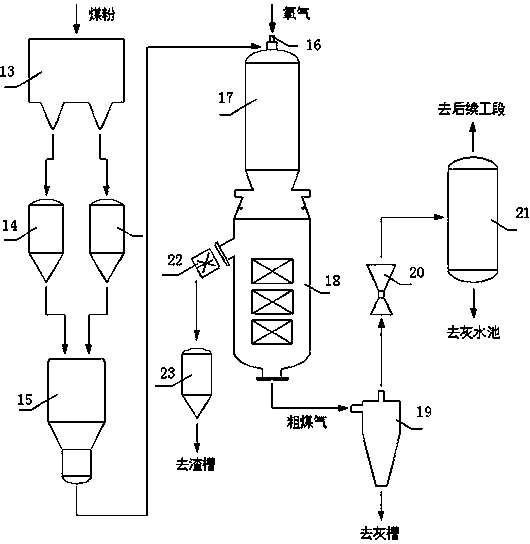
[0043] The invention includes a pulverized coal conveying mechanism, a pressurized gasification mechanism, a coal gas purification mechanism and a slag discharge mechanism. Among them, the pulverized coal delivery mechanism is composed of a pulverized coal storage bin 13, a pulverized coal lock hopper 14, and a pulverized coal delivery tank 15, and the pressurized gasification mechanism is composed of a pulverized coal burner 16, a gasification chamber 17 of a gasifier, and a The recovery device 18 is composed; the gas purification mechanism is composed of a cyclone separator 19, a venturi scrubber 20, and a washing tower 21;

[0044] Process of the present invention is as follows:

[0045] (1) After the raw coal is ground and dried, it enters the pulverized coal silo for storage, and then falls into the pulverized coal lock hopper arranged at the lower part of the silo by its own gravity. The delivery tank adopts the method of discharging from the bottom to carry out pulveri...


PUM


Abstract

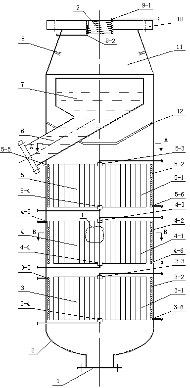
The invention relates to a dry pulverized coal gasification device. The device comprises a pulverized coal silo, pulverized coal lock hoppers, a pulverized coal distributing tank, a gasifier gasification chamber, a coal gasification waste heat recovery device, a cyclone separator, a Venturi scrubber and a scrubbing tower, wherein the pulverized coal silo is used for storing ground and dried pulverized coal; the pulverized coal lock hoppers supplement materials in good time according to the material level of the pulverized coal distributing tank, are installed below the pulverized coal silo and are used for receiving pulverized coal; the pulverized coal distributing tank conveys pulverized coal to the gasifier gasification chamber via a carrier gas; the coal gasification waste heat recovery device is connected at the bottom of the gasifier gasification chamber; the cyclone separator is connected on the coal gasification waste heat recovery device via a pipeline; the Venturi scrubber is connected on the cyclone separator via a pipeline; the scrubbing tower is connected on the Venturi scrubber via a pipeline. Combining a quenching chamber with a convective waste heat boiler into a whole, the device has the advantages that the device fully recovers high-temperature raw coal gases and slag sensible heat, removes fly ash, reduces the investment and improves the heat efficiency.

Description

technical field [0001] The invention relates to coal gasification equipment, in particular to a dry coal powder gasification device. Background technique [0002] The current mainstream entrained bed gasification technology is mainly divided into coal water slurry gasification and dry coal powder gasification. Among them, the typical representative of coal-water slurry gasification is GE gasification technology. The gasification chamber is generally lined with refractory bricks. Due to the limitation of pulping technology and the temperature resistance of refractory bricks, this gasification technology is mainly suitable for coal with good quality. And coal with a lower ash melting point, the gasification temperature is mostly around 1300~1400 °C. Typical representatives of dry pulverized coal gasification are Shell gasification technology and GSP gasification technology. The two technologies have no requirements for coal quality in the dry coal powder conveying mechanism, ...

Claims


Application Information

Patent Timeline
Patent Type & Authority Applications(China)
IPC IPC(8): C10J3/48C10J3/84C10J3/86
CPCC10J3/485C10J3/84C10J3/86C10J2200/09Y02P20/10Y02P20/129
Inventor 陈鹏胡春云吴家桦王晓亮陈慧刘四威
Owner 中国东方电气集团有限公司
Learn More