Glass sheet capable of being inhibited from warping through chemical strengthening
A glass plate, chemical technology, applied in the direction of thin material processing, transportation and packaging, etc., can solve the problem of damage to the flatness of float glass
- Summary
- Abstract
- Description
- Claims
- Application Information
AI Technical Summary
Problems solved by technology
Method used
Image
Examples
Embodiment 1
[0284] (1) Manufacture of float glass
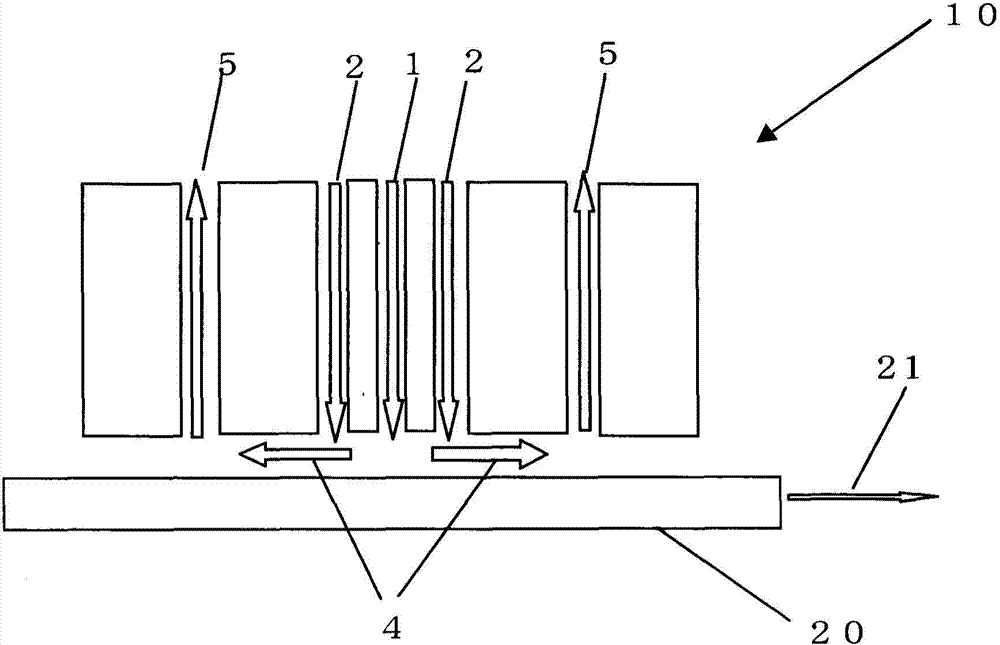
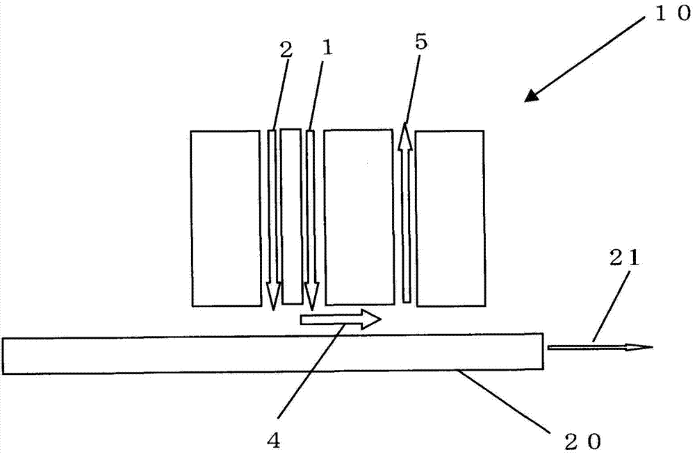
[0285] A glass plate of the glass material C was produced by the float method so that the plate thickness would be 0.8 mm, and this was cut into 50×50 mm to produce a float plate glass. Using the twin-fluid injector 10 used in the atmospheric pressure CVD method, such as figure 1 As shown in the schematic diagram, make the containing SiO 2 The gas or the gas containing hydrogen fluoride is in contact with the surface of the glass plate. In addition, as a reference for each, make containing N 2 The gas is in contact with the surface of the glass.
[0286] That is, for SiO containing 2 gas, will be mixed with 0.09SLM of SiH 4 Nitrogen with 40.4SLM (N 2 ) gas heated to 150 ° C, at a flow rate of 72 cm / sec from figure 1 The central slit 1 shown blows towards the glass plate, and the O of 4.1SLM 2 and N of 36.5SLM 2 Blow the glass plate from the outer slit 2. As a reference, will be mixed with 40.5SLM of nitrogen (N 2 ) gas heate...
Embodiment 2
[0294] Such as Figure 7 As shown in the schematic diagram shown, the glass made by the float method of the glass material C is put into a quartz tube 50 with a volume of 3.2 L, and after the inside of the tube is vacuumed, the glass is filled with 10% H 2 and 90%N 2 mixed gas filling system. Introduce 10% H into the whole system at a flow rate of 1.6L / min 2 and 90%N 2 While heating the mixed gas for 3 minutes, the temperature of the glass plate 51 is raised. 10%H 2 and 90%N 2 The mixed gas is introduced from the gas introduction direction 53 and discharged along the gas discharge direction 54.
[0295] While heating the heated glass plate 51 at 800° C. for 30 seconds, spray HF or HF at the concentration shown in Table 1 to the glass plate 51 at a flow rate of 0.4 L / min using a gas introduction nozzle 52 with an inner diameter of 3.5 to 4.0 mm. Freon. Then, introduce 10% H at a flow rate of 1.6L / min 2 and 90%N 2 While using the mixed gas, the temperature was lowered ...
Embodiment 3
[0302] Such as Figure 9 As shown in the schematic diagram, an experiment was carried out using a glass plate made of glass material C, having a size of 50 mm×50 mm, and a plate thickness of 0.7 mmt. By actuating the slider 64, the sample 63 of the glass plate placed on the sample holder 62 is moved into the reaction container 61 provided in the center of the tubular furnace 60 previously heated at the processing temperature.
[0303] Next, after carrying out the soaking treatment for 30 seconds, introduce the processing gas (Freon) from the introduction pipe 65 along the direction of the gas introduction direction 67 with the temperature conditions, reaction time and gas concentration shown in Table 2, and keep it for a predetermined time. Exhaust in exhaust direction 68 . After the holding time was over, the sample 63 was taken out by using the sample taking rod 66 after subjecting the sample 63 to the predetermined annealing conditions (500° C. for 1 minute and 400° C. for...
PUM
| Property | Measurement | Unit |
|---|---|---|
| thickness | aaaaa | aaaaa |
| thickness | aaaaa | aaaaa |
| glass transition temperature | aaaaa | aaaaa |
Abstract
Description
Claims
Application Information
 - R&D
- Intellectual Property
- Life Sciences
- Materials
- Tech Scout
- Unparalleled Data Quality
- Higher Quality Content
- 60% Fewer Hallucinations
Browse by: Latest US Patents, China's latest patents, Technical Efficacy Thesaurus, Application Domain, Technology Topic, Popular Technical Reports.
© 2025 PatSnap. All rights reserved.Legal|Privacy policy|Modern Slavery Act Transparency Statement|Sitemap|About US| Contact US: help@patsnap.com


