Adhesive thin film, cutting/chip bonding thin film, manufacturing method for semiconductor device and semiconductor device
A chip bonding film and adhesive film technology, which is applied in the direction of film/sheet adhesive, semiconductor/solid device manufacturing, semiconductor device, etc., can solve the problem of paste adhesive coating amount, coating shape deviation, and difficulty in uniformity Solve problems such as long time, achieve the effect of improving the yield, good production efficiency, and preventing the decline of communication speed
- Summary
- Abstract
- Description
- Claims
- Application Information
AI Technical Summary
Problems solved by technology
Method used
Image
Examples
no. 1 approach
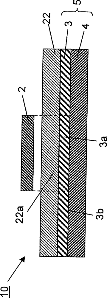
[0073] In the first embodiment, if figure 1 As shown, a dicing / die-bonding film in which an adhesive film 22 is laminated on a dicing film 5 obtained by laminating an adhesive layer 3 on a base material 4 will be described below as an example. In this embodiment mode, a mode in which the electrical connection between the adherend and the first semiconductor element is realized by wire bonding connection will be described.
[0074]
[0075] The adhesive film 22 contains a thermoplastic resin and a thermosetting resin (described later), and the abundance ratio of the thermoplastic resin is 10% or more and 30% or less. The lower limit of the abundance ratio of the thermoplastic resin is preferably 15% or more. The upper limit of the abundance ratio of the thermoplastic resin is preferably 25% or less. An appropriate viscosity can be imparted to the adhesive film 22 by setting the abundance ratio of the thermoplastic resin within the above range. As a result, the followabilit...
no. 2 approach
[0201] In the first embodiment, the first semiconductor element is fixed on the adherend by an adhesive film, and the electrical connection between the two is realized by wire bonding. However, in the second embodiment, by using The flip-chip connection of the protruding electrodes on the components realizes the fixation and electrical connection between the two. Therefore, the second embodiment differs from the first embodiment only in the fixing method in the first fixing step, and the difference will be mainly described below.
[0202] (First fixed process)
[0203] In this embodiment, in the first fixing step, the first semiconductor element 41 is fixed on the adherend 1 by flip-chip connection (refer to Figure 4A ). The flip-chip connection is so-called face-down mounting in which the circuit surface of the first semiconductor element 41 faces the adherend 1 . A plurality of protruding electrodes 43 such as bumps are provided on the first semiconductor element 41 , an...
Embodiment 1~8 and comparative example 1~4
[0220] (Production of adhesive film)
[0221] Acrylic resin A, acrylic resin B, epoxy resin A, epoxy resin B, phenolic resin, silicon dioxide and a thermosetting catalyst are dissolved in methyl ethyl ketone in the ratio shown in Table 1 to prepare a concentration of 40 to 50% by weight solution of the adhesive composition.
[0222] This adhesive composition was applied to a release-treated film comprising polyethylene terephthalate film having a thickness of 50 μm after silicone release treatment as a release liner, and then dried at 130° C. for 2 minutes , thereby producing adhesive films having thicknesses shown in Table 1 below.
[0223] In addition, the details of the abbreviations and components in Table 1 below are as follows.
[0224] Acrylic resin A: SG-700AS manufactured by Nagase Chemtex Co., Ltd.
[0225] Acrylic resin B: SG-70L manufactured by Nagase ChemTex Co., Ltd.
[0226] Epoxy resin A: KI-3000 manufactured by Tohto Kasei Co., Ltd.
[0227] Epoxy resin B...
PUM
| Property | Measurement | Unit |
|---|---|---|
| storage modulus | aaaaa | aaaaa |
| particle size | aaaaa | aaaaa |
| thickness | aaaaa | aaaaa |
Abstract
Description
Claims
Application Information
 - R&D
- Intellectual Property
- Life Sciences
- Materials
- Tech Scout
- Unparalleled Data Quality
- Higher Quality Content
- 60% Fewer Hallucinations
Browse by: Latest US Patents, China's latest patents, Technical Efficacy Thesaurus, Application Domain, Technology Topic, Popular Technical Reports.
© 2025 PatSnap. All rights reserved.Legal|Privacy policy|Modern Slavery Act Transparency Statement|Sitemap|About US| Contact US: help@patsnap.com


