Method for the selection of physical objects in a robot system

Active Publication Date: 2013-06-13
MP ZENROBOTICS OY
View PDF20 Cites 96 Cited by
  • Summary
  • Abstract
  • Description
  • Claims
  • Application Information

AI Technical Summary

Benefits of technology

This patent describes a system for improving the selection of objects from an operating space of a robot. The system includes a verification position for the robot arm, a learning system, and a system for calculating an efficient way to move the robot arm to the determined target location. The learning systems use sensor data to improve the operation of the system as new attempts at gripping objects are made, and the effect of the invention is to improve the quality of selecting objects from the operating space of the robot.

Problems solved by technology

While programming the robot to perform repetitive tasks is relatively easy, there are difficult problems in automatically manipulating objects, especially related to recognizing the objects from a varying environment or an environment crowded with other objects, and manipulating an object which resides among other objects.
Namely, other objects may cover the object partially or in whole, thus making it difficult to pin down the exact location of the object to instruct the robot arm to move to, or the other objects can obstruct the movements of a robot hand thereby making pre-programmed movements unsuitable for the task.
However, there are possibilities for error in determining of the type of an object.
For example, image recognition algorithms can produce false results, identifying an object as that of a wrong type.
Further, even if the object has been correctly recognized, the gripper could fail to grip the intended object, for example, if the intended object is obscured by another object which could get gripped instead, or if the gripper is not moved to the right position before gripping as a result of inaccuracies in controlling the robot arm.
There is also the possibility that several objects are inadvertently gripped at the same time, for example, if the objects are located close together or they are stuck together.

Method used


Image

  • Method for the selection of physical objects in a robot system
  • Method for the selection of physical objects in a robot system
  • Method for the selection of physical objects in a robot system

Examples


Embodiment Construction

[0048]Reference will now be made in detail to the embodiments of the present invention, examples of which are illustrated in the accompanying drawings.

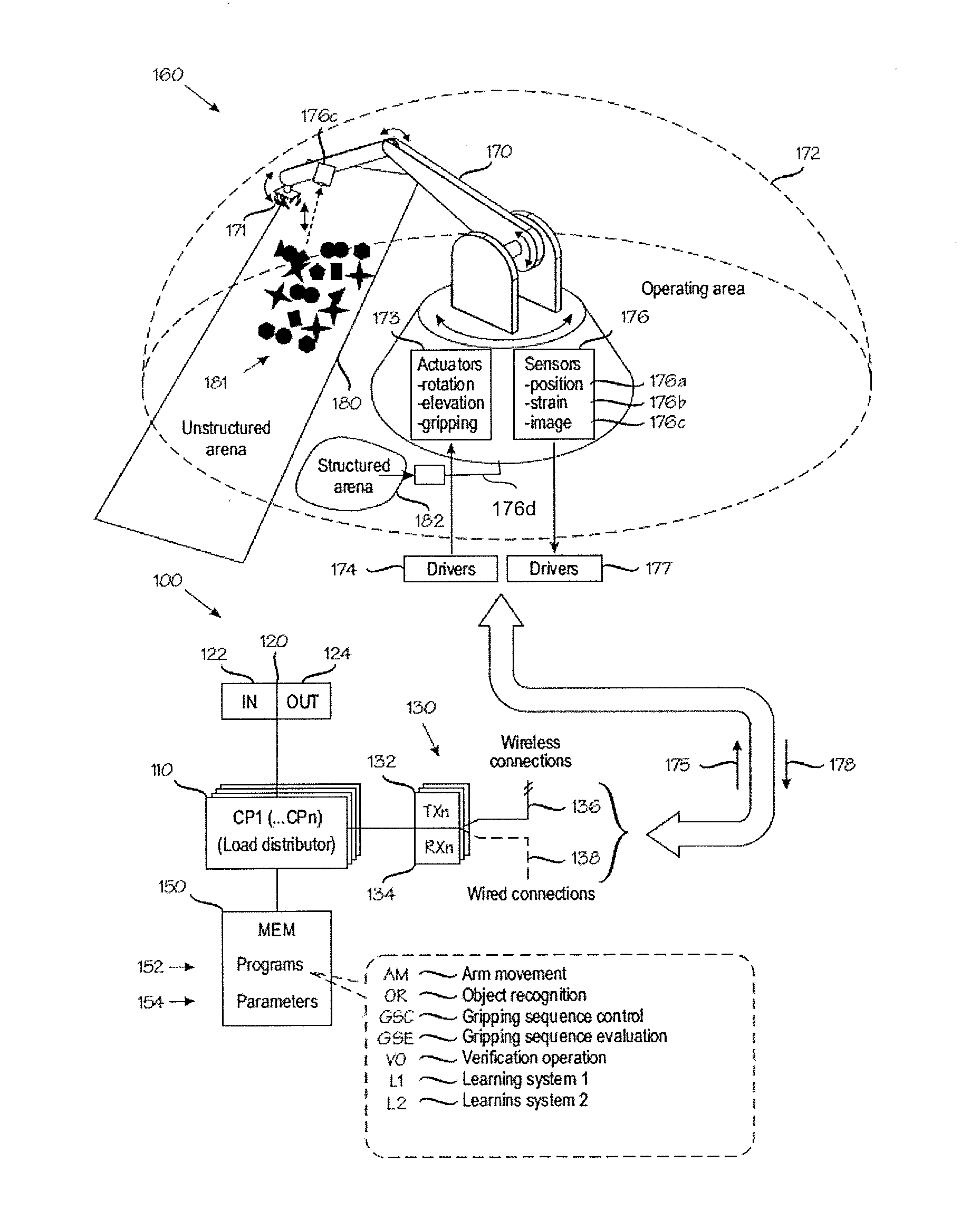
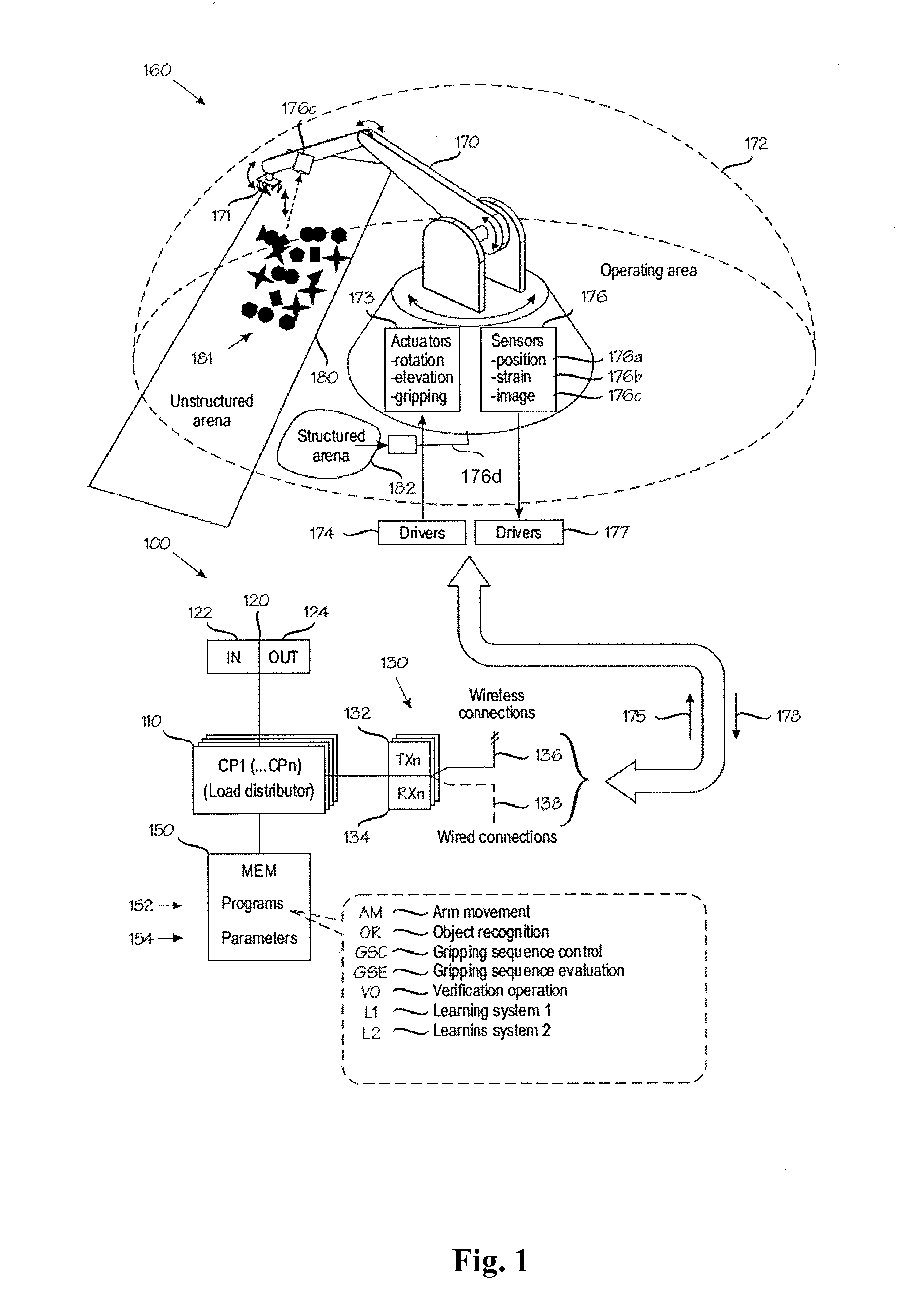
[0049]FIG. 1 is a block diagram illustrating a robot system for the selection of physical objects in one embodiment of the invention. In FIG. 1 a data processing apparatus 100, in short an apparatus, comprises a central processing unit (CP) 110 and memory 150. Some embodiments of the invention employ multiple processors CP1 through CPn, plus a load distribution unit for distributing load among the multiple processors. The one or more processors control the robot arm by executing programs 152 stored in one or more memories 150. During execution, the programs 152 set up and update various parameters and variables 154 in the memory 150. Some parameters may be represented, for example, as tables, arrays, lists, sparse or dense matrixes or other data structures.

[0050]In addition, the data processing apparatus 100 comprises or utilizes exte...


PUM


Abstract

A method in which an apparatus receives first sensor data from first sensors and determines a target position from the data, the target position may be a position in space or an orientation of a gripper in a robot arm First instructions are issued to the robot arm or the gripper in order to move a gripper to the target position. Force feedback sensor data is received from force feedback sensors associated with either the robot arm or the gripper or from the first sensors. A failure in carrying out the first instructions is determined Second sensor data is received from the at least one first sensor. Successful gripping of an object is determined from the second sensor data.

Description

BACKGROUND OF THE INVENTION[0001]1. Field of the Invention[0002]The present invention relates to systems and methods used for manipulating physical objects. In particular, the present invention relates to a method for the selection of physical objects in a robot system.[0003]2. Description of the Related Art[0004]Robot systems have widely been used in many industries to perform repetitive tasks that require little capability to actually model visually or cognitively physical objects being manipulated or that require little skill to take a hold on and to move. Robots can also be built to work in environments hostile to human floor workers or to be able to work with material hazardous to humans such as toxic or radioactive materials, waste or massive objects. It is desirable to make such robot systems as autonomous as possible to minimize the amount of human involvement needed.[0005]When the aim is to have the robot arm to manipulate objects, the robot arm is commonly equipped with a ...

Claims


Application Information

Patent Timeline
IPC IPC(8): B25J9/00B25J13/08
CPCB25J9/1694B25J13/085B25J9/00B25J13/08B25J9/1697G05B2219/39528G05B2219/40053G05B2219/40571Y10S901/09
Inventor VALPOLA, HARRILUKKA, TUOMAS
Owner MP ZENROBOTICS OY
Why Eureka
Try Eureka