knife holder

A tool holder and tool handle technology, which is applied in the field of tool holders for processing the outer diameter of slender shafts, can solve problems such as straightness indicators that cannot meet the requirements, bending deformation of slender shafts, and hindering parts processing, etc., to achieve good processing effects and eliminate Bending deformation, the effect of ensuring the processing quality

Active Publication Date: 2016-08-17
HARBIN DONGAN ENGINE GRP
View PDF7 Cites 0 Cited by
  • Summary
  • Abstract
  • Description
  • Claims
  • Application Information

AI Technical Summary

Problems solved by technology

When processing such parts, due to the weight of the slender shaft itself, after installation, the slender shaft will produce a certain bending deformation, and the processing position is not along the generatrix of the slender shaft, but forms a curve, resulting in After processing, the margin removed in the middle is less than that at both ends, the long axis of the wire is shuttle-shaped after processing, and the straightness index cannot meet the requirements
The current solution is to add a support structure in the middle of the slender shaft. However, this method will also produce a certain amount of bending between the support point and the installation position, which cannot completely solve the problem of bending deformation. At the same time, the added support structure often It will hinder the processing of parts, and it needs to be adjusted at any time, and the axis position of the long axis of the line before and after adjustment must be kept unchanged, the operation is cumbersome and the efficiency is low

Method used


Image

  • knife holder
  • knife holder
  • knife holder

Examples


Embodiment Construction

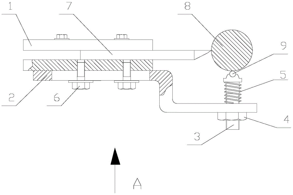
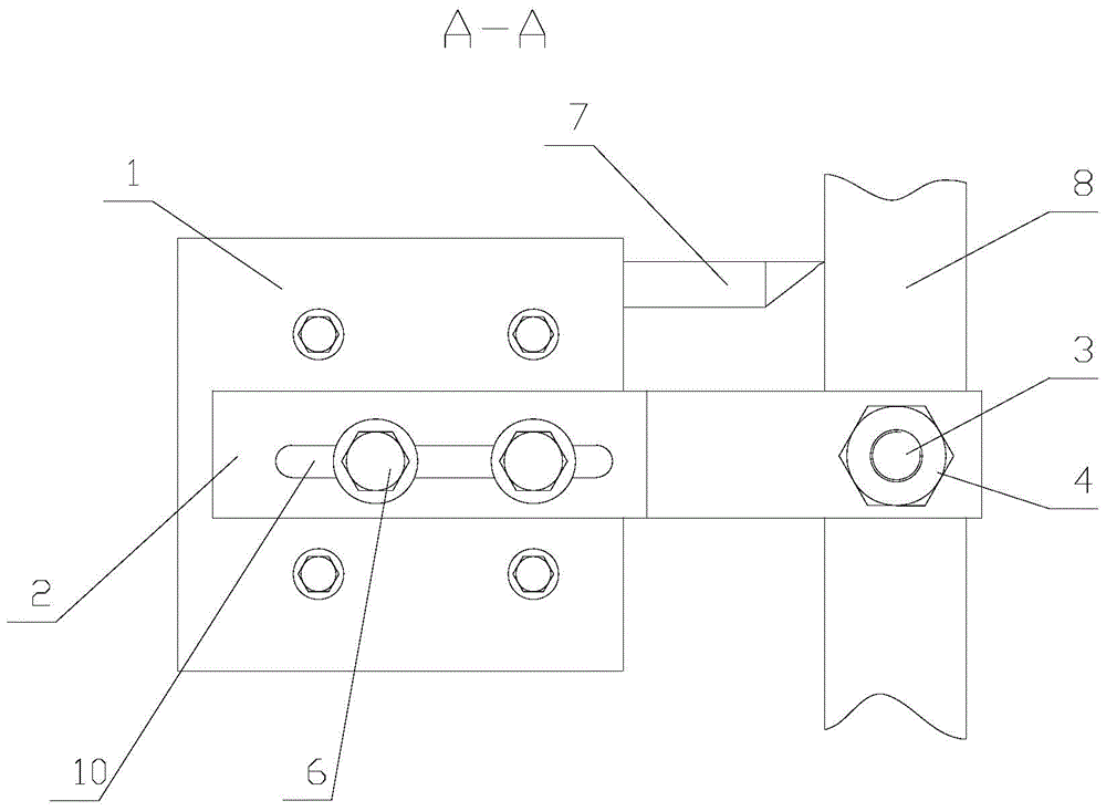
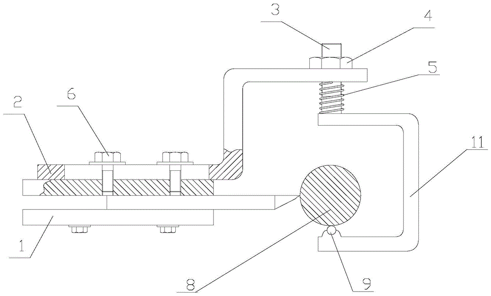
[0011] As shown in the figure, the knife holder includes a handle seat 1, a support arm 2, an adjustment screw pile 3, an adjustment nut 4, a compression spring 5, and a fastening bolt 6, and a turning tool 7 is installed on the handle seat 1. The support arm 2 is fixed on the lower part of the handle seat 1 by the fastening bolt 6, the front end of the support arm 2 extends to the bottom of the elongated shaft 8 to be processed, and a through hole is arranged below the axis of the elongated shaft 8, and the adjustment screw The pile 3 passes through the through hole of the support arm 2 and is provided with an adjustment nut 4 matched with the adjustment screw pile 3 at the bottom of the support arm 2, and a compression spring 5 is provided at the top, and one end of the compression spring 5 is pressed on the support arm 2, the other end is pressed on the step provided on the adjustment screw pile 3, and the adjustment screw pile 3 can be connected with the slender shaft 8 to ...


PUM


Abstract

The invention relates to a knife rest. The knife rest comprises a knife handle seat, a support arm, a regulating dowel, a regulating nut, a compression spring and a fastening bolt, wherein a turning tool is arranged on the knife handle seat, the support arm is fixed on the lower part of the knife handle seat through the fastening bolt, the front end of the support arm extends to the lower part of a slender shaft to be processed, the regulating dowel penetrates through a through hole in the support arm, the lower part of the support arm is provided with the regulating nut matched with the regulating dowel, the upper part of the support arm is provided with the compression spring, one end of the compression spring presses the upper surface of the support arm, the other end of the compression spring presses a step arranged on the regulating dowel, and the top end of the regulating dowel is provided with a round ball which can rotate freely. According to the knife rest, before processing, each component is regulated, and then processing operation can be carried out; no regulation is needed halfway, the use is convenient, the efficiency is high, and the processing effect is good.

Description

technical field [0001] The invention relates to a tool holder, in particular to a tool holder for processing the outer diameter of a slender shaft. Background technique [0002] In mechanical processing, the outer diameter of shaft parts is usually processed by a lathe. One end of the workpiece is installed on the chuck of the lathe, and the other end is pushed on the top through the center hole. The workpiece is driven to rotate by the chuck, and the turning tool is installed on the tool holder. On the machine tool, it moves linearly along the lathe guide rail to complete the machining of the outer diameter of shaft parts. However, in practical applications, it is necessary to process the outer diameter of the slender shaft, such as the transmission shaft of a helicopter, whose length-to-diameter ratio L / D is greater than 20, or even 40. When processing such parts, due to the weight of the slender shaft itself, after installation, the slender shaft will produce a certain b...

Claims


Application Information

Patent Timeline
Patent Type & Authority Patents(China)
IPC IPC(8): B23B21/00
CPCB23Q1/262B23Q1/40
Inventor 于海龙
Owner HARBIN DONGAN ENGINE GRP
Why Eureka
Try Eureka