Combined cutter and separable cutting method of ceramic substrate LED

A ceramic substrate, combined technology, used in manufacturing tools, fine working devices, stone processing equipment, etc., can solve problems such as rapid wear, large cutting heat, and pulling on chip gold wires.

Inactive Publication Date: 2014-09-10
HONGLI ZHIHUI GRP CO LTD
View PDF4 Cites 3 Cited by
  • Summary
  • Abstract
  • Description
  • Claims
  • Application Information

AI Technical Summary

Problems solved by technology

In general, the resin-based diamond grinding wheel has low hardness and good self-sharpening. It is suitable for grinding harder and more brittle materials, and the obtained surface accuracy is higher, but it wears faster; the metal-based diamond grinding wheel is the opposite
However, when glue has been dispensed on the surface of the CHIP LED chip, if the resin-based diamond grinding wheel is used, there will be a situation where the silicone sticks to the knife, so that part of the diamond blade cannot participate in the cutting, which affects the cutting effect of the ceramic. The common cutting problems are The cutting surface is inclined into a trapezoidal surface; at the same time, the cutting force of the grinding process is relatively large, which is easy to pull the gold wire on the chip, and the large cutting force brings large cutting heat, which is easy to burn out the silicone
The use of metal-based diamond grinding wheels can cut silicone smoothly, which can reduce or avoid the situation of silicone sticking to a certain extent, but the hardness of the grinding wheel is high, which intensifies the cracking of the ceramic substrate, forming a large number of cracks, chipping and protrusions, etc.
A single diamond grinding wheel has been difficult to solve the mixed cutting of brittle materials and plastic materials

Method used


Image

  • Combined cutter and separable cutting method of ceramic substrate LED
  • Combined cutter and separable cutting method of ceramic substrate LED
  • Combined cutter and separable cutting method of ceramic substrate LED

Examples


Embodiment Construction

[0034] The present invention will be further described in detail below in conjunction with the accompanying drawings and specific embodiments.

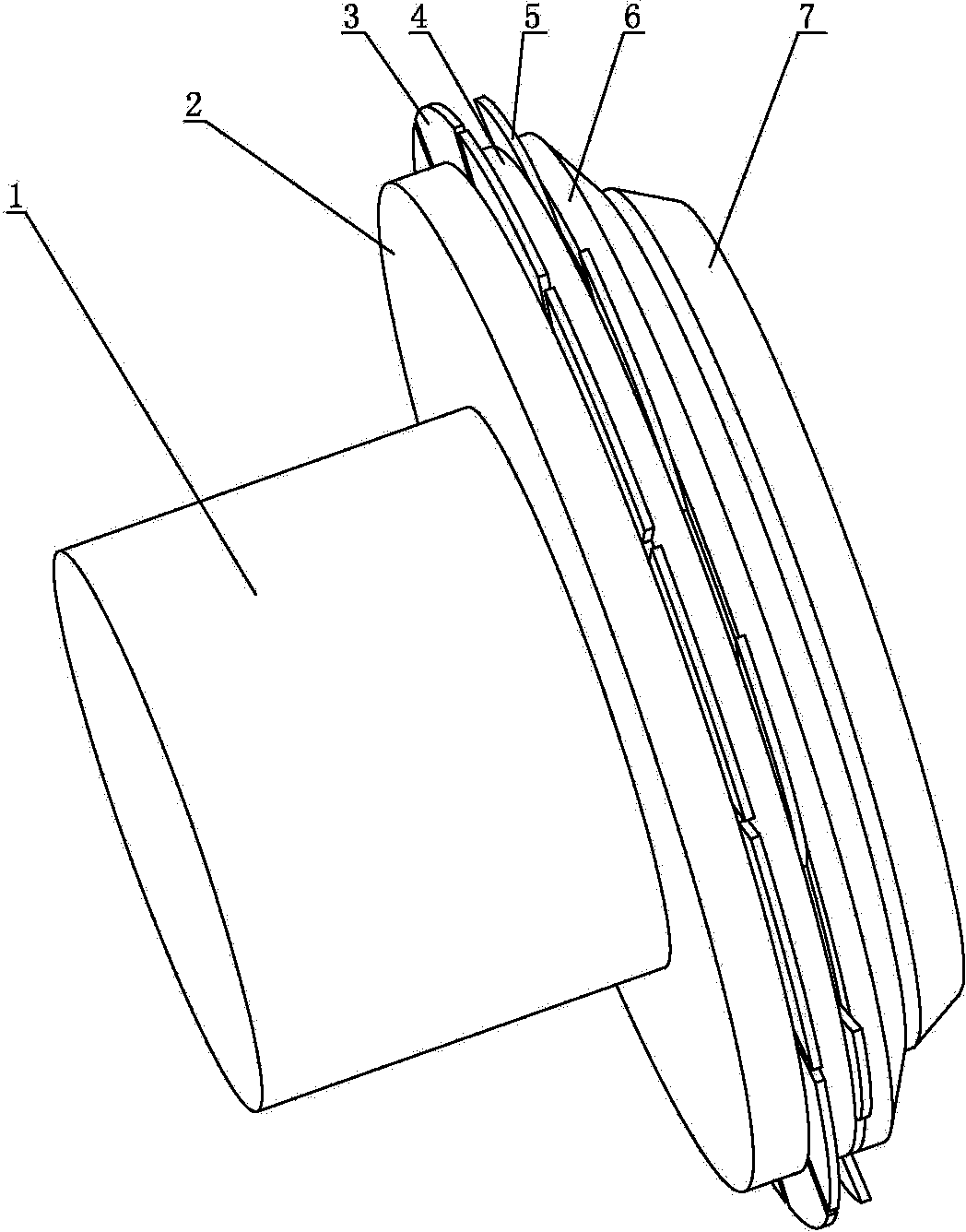
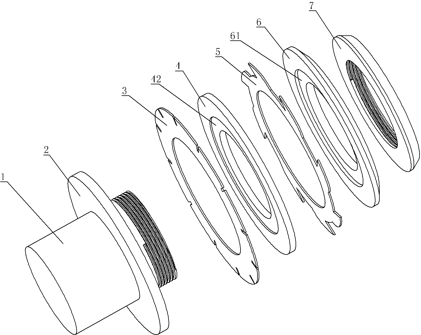
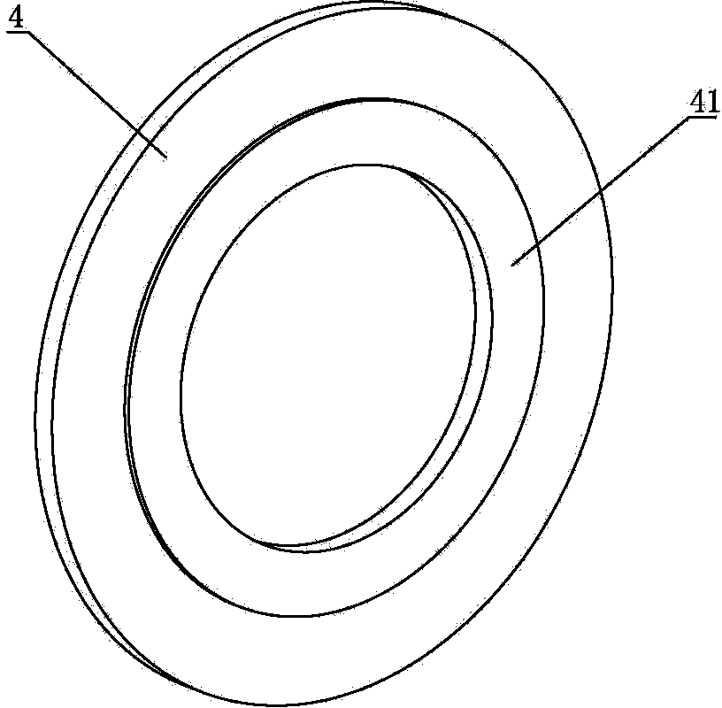
[0035] Such as Figure 1 to Figure 2As shown, the combined tool includes a main shaft 1, a main shaft flange 2, a grinding wheel 3, a flange gasket 4, a disc milling blade 5, a gasket 6 and a locking device, and the main shaft flange 2 is fixed on the main shaft 1, generally the two are integrated, the grinding wheel 3, the flange gasket 4, the disc milling blade 5, and the gasket 6 are set on the main shaft 1 from the back to the front, and the flange gasket 4 is used to install the grinding wheel 2. The locking device is a lock nut, and the lock nut 7 is connected to one end of the main shaft 1 through threads, and is used to lock and fix the grinding wheel 3, the flange gasket 4, the disc milling blade 5, and the gasket 6, among which , the thickness of the flange gasket 4 is flexibly selected according to the size of the LED, the...


PUM


Abstract

The invention discloses a combined cutter and separable cutting method of a ceramic substrate LED. The combined cutter comprises a main shaft, a main shaft flange, a grinding wheel sheet, a flange gasket, a disk shaped milling sheet, a gasket and a locking device, wherein the main shaft flange, the grinding wheel sheet, the flange gasket, the disk shaped milling sheet, the gasket and the locking device are sequentially arranged on the main shaft; the diameter of the grinding wheel sheet is more than that of the disk shaped milling sheet. The cutting method comprises the following steps: transversely cutting and lengthways cutting an LED sheet through the combined cutter; grinding and processing the ceramic substrate through the grinding wheel sheet during cutting; milling a rubber layer through the disk shaped milling sheet, wherein the grinding wheel sheet and the disk shaped milling sheet work at the same time. According to the method, the cutter of different forms and different processing methods are utilized to separately cut the rubber layer and the ceramic substrate, and thus the cutting efficiency and quality are improved.

Description

technical field [0001] The invention relates to a combined cutter with different diameters and shapes and a method for separately cutting ceramic substrate LEDs based on the combined cutter. Background technique [0002] At present, the calorific value of a single high-power LED device increases significantly with the power. In order to solve the problem of heat dissipation, one of the solutions is to use metal or ceramic substrates. Among them, COB LEDs can use metal substrates or ceramic substrates, while CHIP LEDs Mainly use ceramic substrate. When CHIP LED is produced, it usually produces a large sheet of glue that has been dispensed, and then cuts the sheet, but ceramics are brittle and hard materials, so they can only be cut with a harder diamond wheel, and the cutting method is grinding. [0003] Diamond grinding wheels can be divided into metal-based diamond grinding wheels and resin-based diamond grinding wheels according to different binders. The nature of the sub...

Claims


Application Information

Patent Timeline
IPC IPC(8): H01L33/20
CPCB24B27/06B28D5/022H01L33/483H01L2933/0033
Inventor 何永泰王跃飞乔翀李坤锥李恒彦熊毅
Owner HONGLI ZHIHUI GRP CO LTD
Why Eureka
Try Eureka