
High-temperature powder bed system for laser additive manufacture

A laser additive and high-temperature technology, applied in the field of additive manufacturing, can solve the problems of low heating power of the iron core, shorten the service life, and lose heat energy, etc., and achieve the effects of uniform temperature distribution, excellent quality, and uniform heating

Active Publication Date: 2014-08-20
HUAZHONG UNIV OF SCI & TECH
View PDF5 Cites 41 Cited by
  • Summary
  • Abstract
  • Description
  • Claims
  • Application Information

AI Technical Summary

Problems solved by technology

However, the overall working space is in the furnace body, and there is no cooling device after heating, and the equipment components are at high temperature, thereby reducing their service life
In the above two inventions, the powder bed preheating method in the field of additive manufacturing uses traditional resistance wire heating. The principle of resistance wire heating is to use electric current to generate heat through resistance wire, and the heat is transferred to the area that needs to be heated in the form of heat transfer. On the object, part of the thermal energy has been lost during the heat transfer process, and another part of the thermal energy is dissipated into the air at the same time. The utilization rate of thermal energy in this way is very low.
Electromagnetic heating can improve energy utilization efficiency to a certain extent. Due to the material selection and power control system of ordinary household induction cookers, the heating power of the iron core is relatively small (within 2200 watts), and the maximum heating temperature can only reach about 300 degrees. Requirements for high temperature preheating in the field of material manufacturing

Method used


Image

  • High-temperature powder bed system for laser additive manufacture
  • High-temperature powder bed system for laser additive manufacture
  • High-temperature powder bed system for laser additive manufacture

Examples


Embodiment Construction

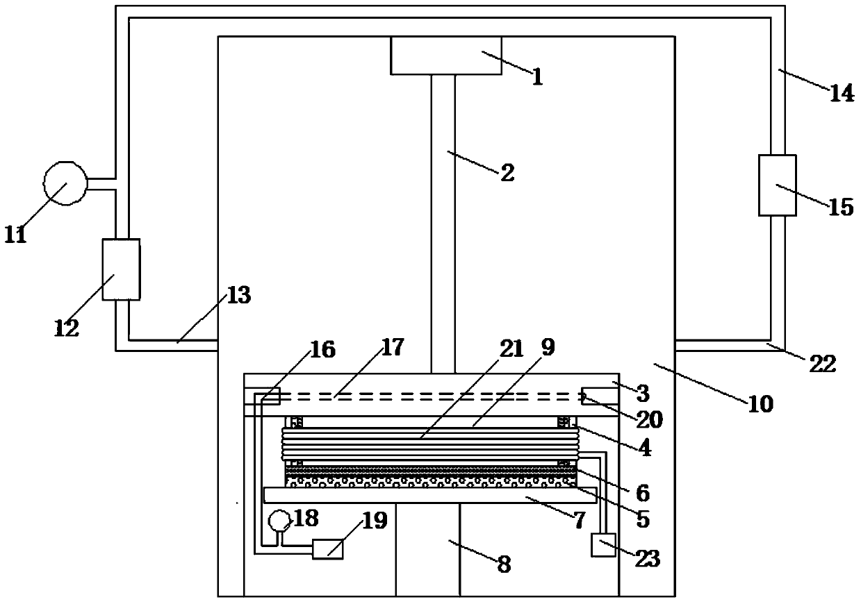
[0020] like figure 1 As shown, the system of the present invention includes a working chamber 10, a laser 1, a workbench 3, an electromagnetic heating layer, a thermal insulation component, a laminar flow uniform temperature component and a cooling channel.

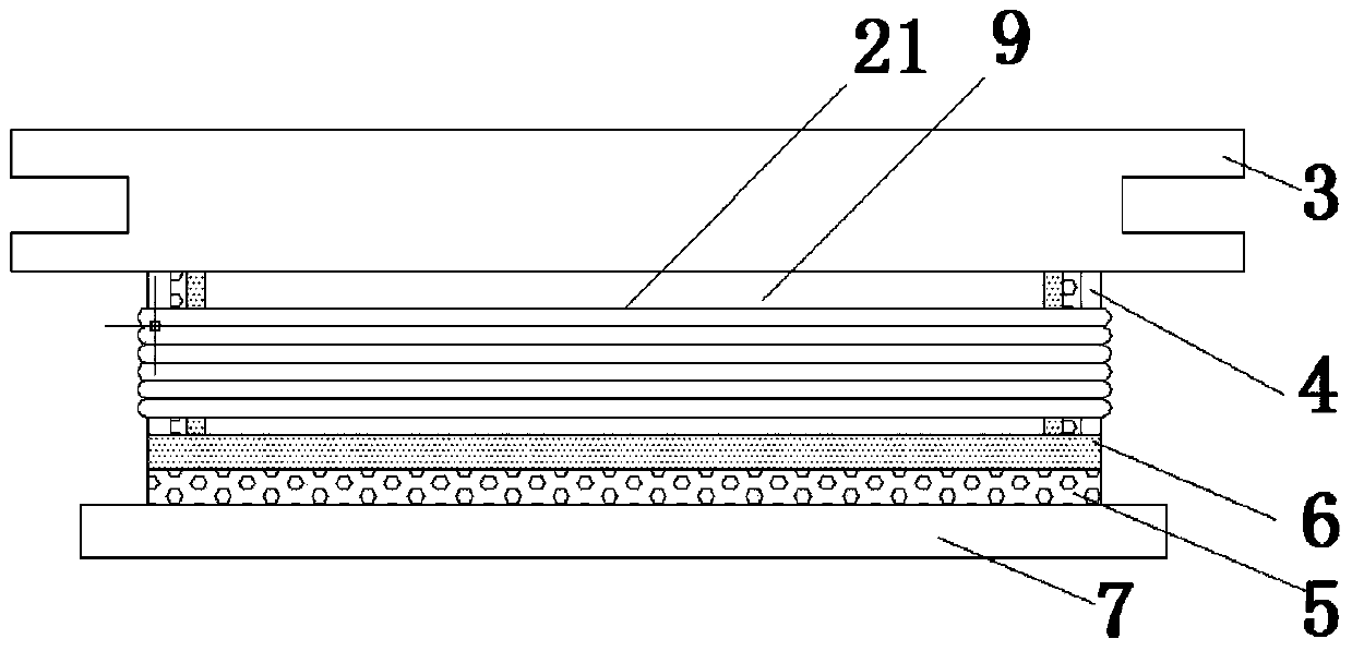
[0021] Workbench 3 can adopt lifting type, is installed in the working cavity 10, specifically can be connected with ball screw 8 by its lower top plate 7, plays the lifting of controlling whole workbench 3. The electromagnetic heating layer is the main heat source, and it is placed on the lower surface of the workbench 3 and tightly attached to it. The heat can be directly conducted to the workbench 3 like this.

[0022] The electromagnetic heating layer is mainly composed of an electromagnetic induction plate 9 and an electromagnetic coil 21 .

[0023] In the actual working process, the working chamber 10 needs to be heated to a very high temperature. In order to protect the additive manufacturing equipment from high ...


PUM


Abstract

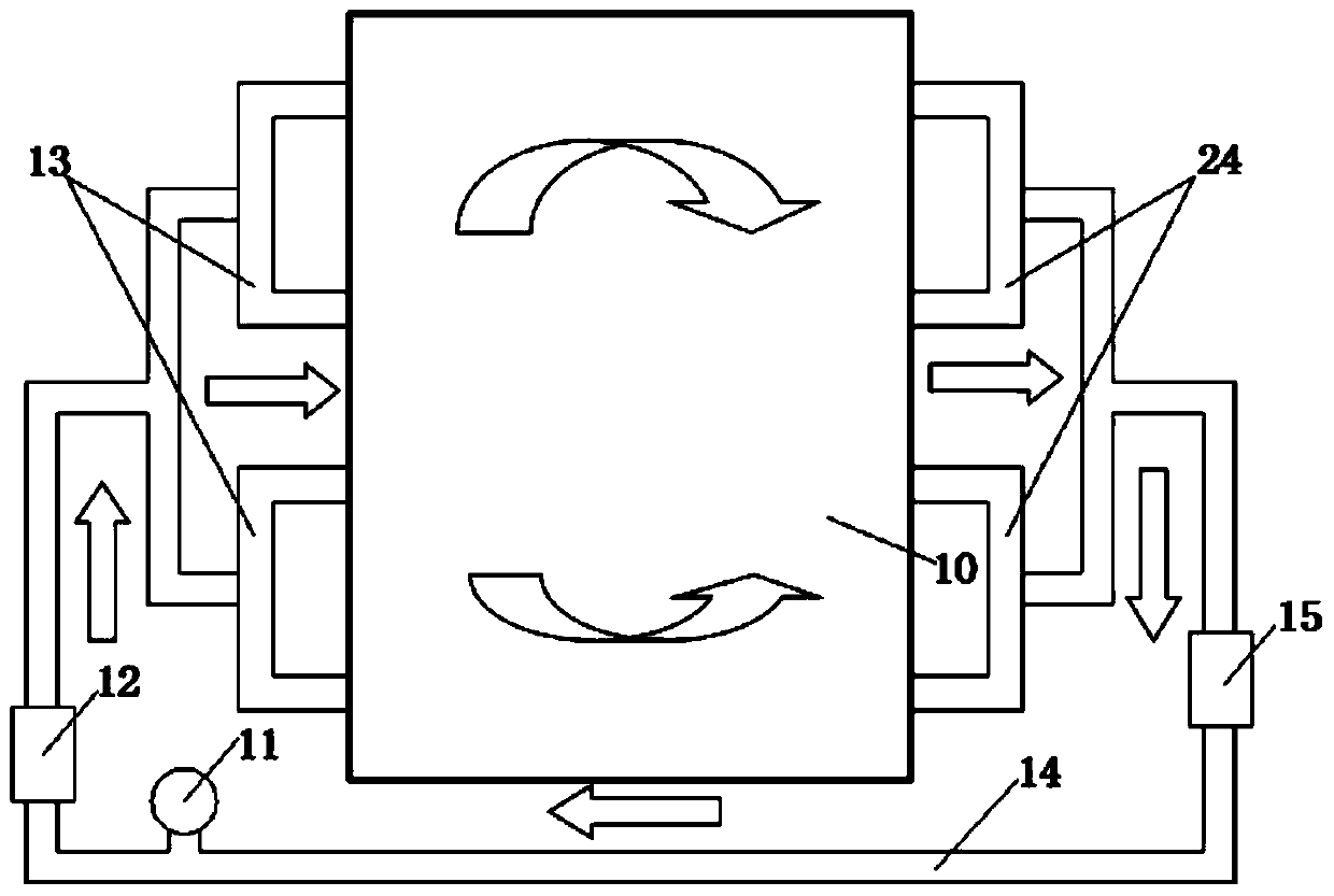
The invention discloses a high-temperature powder bed system for laser additive manufacture. The system comprises a working cavity, a laser device, a workbench, an electromagnetic heating layer, a heat insulation component and a laminar flow temperature uniforming component, the workbench is arranged in the working cavity, the electromagnetic heating layer is mainly composed of an electromagnetic induction plate and a coil, the electromagnetic heating layer is placed on the lower surface of the workbench and is attached to the workbench, and heat can be directly conducted to the workbench. A cooling flow way is arranged in the workbench, the bottom face and the side face of the electromagnetic heating layer are surrounded by the heat insulation component, and heat insulation and heat preservation of the electromagnetic heating layer can be achieved. The laminar flow temperature uniforming component is arranged outside the working cavity and used for achieving air flow circulation in the working cavity, and even temperature distribution of the workbench can be achieved. According to the part size, the work table board can be heated to be at the high temperature, heat preservation is performed, and temperature uniformization and the cooling functions after machining can be achieved. The aims of protecting the systems, and improving energy utilization rate and heating efficiency can be achieved.

Description

technical field [0001] The invention belongs to the field of additive manufacturing, and in particular relates to a system for realizing conduction zone heating and heat preservation of a substrate of a high-temperature powder bed, temperature cooling, and uniform distribution of the temperature field of a circulating air flow. technical background [0002] Additive Manufacturing (AM) is a widely used rapid prototyping technology. First, the computer three-dimensional solid model of the required parts is designed by CAD three-dimensional modeling software, and then decomposed into a series of two-dimensional parts according to the process requirements according to a certain thickness. Cross-section, that is to change the original three-dimensional information into two-dimensional plane information, then scan layer by layer, superimpose layer by layer, and finally form the required prototype or part. [0003] In the process of forming metal and ceramic parts by additive manuf...

Claims


Application Information

Patent Timeline
IPC IPC(8): B22F3/105
CPCY02P10/25
Inventor 魏青松史玉升张洁刘洁李伟李帅
Owner HUAZHONG UNIV OF SCI & TECH
Learn More