
Ultra-low ohm contact resistance graphene transistor and preparation method thereof

An ohmic contact and graphene technology, applied in transistors, semiconductor/solid-state device manufacturing, circuits, etc., can solve problems such as limiting the development of GFETs, and achieve the effect of reducing contact resistance and increasing the maximum oscillation frequency

Active Publication Date: 2017-02-01
THE 13TH RES INST OF CHINA ELECTRONICS TECH GRP CORP
View PDF4 Cites 3 Cited by
  • Summary
  • Abstract
  • Description
  • Claims
  • Application Information

AI Technical Summary

Problems solved by technology

But the maximum oscillation frequency f max still low, typically less than 50 GHz, f max Represents the limit of the transistor's amplification capability, so the low f max It limits the practical application of GFET and becomes a bottleneck restricting the development of GFET

Method used


Image

  • Ultra-low ohm contact resistance graphene transistor and preparation method thereof
  • Ultra-low ohm contact resistance graphene transistor and preparation method thereof
  • Ultra-low ohm contact resistance graphene transistor and preparation method thereof

Examples


Embodiment 1

[0040] The ultra-low-ohm contact resistance graphene transistor comprises a substrate 1 and a source 5 and a drain 7 located on the substrate 1, and is characterized in that: a channel region is formed between the source 5 and the drain 7, and the channel region From bottom to top are: graphene layer 2 , dielectric layer 3 and gate 6 .

[0041] The preferred technical solution is that the substrate 1 is SiC, Si, SiO 2 , glass or flexible insulating substrates. The flexible insulating substrate is preferably polyethylene terephthalate, polyimide or polydimethylsiloxane substrate.

[0042] A further preferred technical solution is that the material of the dielectric layer 3 is HfO 2 , ZrO 2 , La 2 o 3 、Al 2 o 3 , TlO 2 , SrTiO 3 , LaAlO 3 , Y 2 o 3 , HfO x N y , ZrO x N y , La 2 o x N y 、Al 2 o x N y 、TiOx N y , SrTiO x N y , LaAlO x N y , Y 2 o x N y , one or more mixtures of silicates, where x=0.5-3, Y=0-2; the source (5), drain (7) and gate (6) a...

Embodiment 2

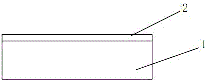
[0045] 1. A graphene layer 2 is formed on the substrate 1. The substrate of this embodiment is made of SiC material, such as figure 2 shown;

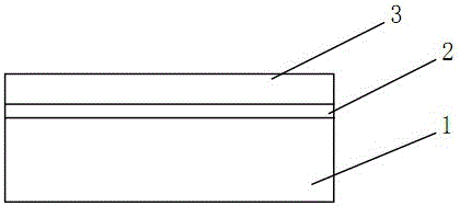
[0046] ② Deposit 4 nm Al on the graphene layer 2, and self-oxidize to form Al 2 o 3 , as dielectric layer 3, such as image 3 shown;

[0047] ③ On the dielectric layer 3, the channel area is covered by the photoresist pattern 4, such as Figure 4 shown;

[0048] ④Using the photoresist pattern 4 as a mask, the BOE solution wet etching removes the exposed dielectric layer 3 outside the channel area, such as Figure 5 shown;

[0049] 5. Use the photoresist pattern 4 as a mask, oxygen plasma etching the exposed graphene layer 2 outside the channel region, as Figure 6 shown;

[0050] ⑥Electron beam evaporation of 100 nm Au as source and drain ohmic contact metal to form ohmic contact metal layer 8, peel off, and remove photoresist pattern 4, such as Figure 7 , 8 shown;

[0051] ⑦ Cover the required source and drain regions thro...

Embodiment 3

[0055] ① Form a graphene layer 2 on the substrate 1, the substrate of this embodiment is SiO 2 Material; the graphene layer adopts the single-layer graphene prepared by tearing method, such as figure 2 shown;

[0056] ② Deposit 2 nm Ti on the graphene layer 2, and auto-oxidize to form TiO 2 , as a seed layer, on which HfO was deposited using ALD (atomic layer deposition) 2 , forming a dielectric layer 3, such as image 3 shown;

[0057] ③ On the dielectric layer 3, the channel area is covered by the photoresist pattern 4, such as Figure 4 shown;

[0058] ④ Use photoresist pattern 4 as a mask, use HNO 3 with H 2 o 2 The mixed solution wet etching removes the exposed dielectric layer 3 outside the channel area, such as Figure 5 shown;

[0059] 5. Use the photoresist pattern 4 as a mask, oxygen plasma etching the exposed graphene layer 2 outside the channel region, as Figure 6 shown;

[0060] ⑥Electron beam evaporation of 50 nm Pd as source and drain ohmic contact...


PUM


Abstract

The invention discloses an ultralow ohmic contact resistance graphene transistor comprising a substrate, and a source and a drain which are located on the substrate. A channel region is formed between the source and the drain. The channel region comprises a graphene layer, a dielectric layer and a gate from down to up successively. The preparation method of the ultralow ohmic contact resistance graphene transistor comprises the following steps: (1) the graphene layer is formed; (2) the dielectric layer is deposited; (3) on the dielectric layer, the channel region is covered with a photoresist pattern; (4) the exposed dielectric layer is corroded; (5) the exposed graphene layer is etched; (6) a source-drain ohmic contact metal is evaporated to form an ohmic contact metal layer; (7) the required source and drain regions are covered with the photoresist pattern; (8) the source and the drain are formed; (9) and the gate is formed. According to the method of the invention, the one-dimensional linear contact between the source-drain ohmic contact metal and the graphene can be realized so as to greatly reduce the contact resistance between the graphene and the metal, so that the maximum oscillation frequencycan be increased, and the applications of the graphene field effect transistor can be facilitated.

Description

technical field [0001] The invention relates to the technical field of semiconductor devices. Background technique [0002] The ideal two-dimensional crystal structure material graphene has ultra-high carrier mobility (10 6 cm 2 / V s), ultra-high carrier saturation drift velocity (5×10 7 cm / s), which is ideal for making high-frequency transistors. [0003] Cutoff Frequency of Graphene Field Effect Transistor (GFET) f T Has reached 427 GHz, which is close to the best silicon-based transistors. But the maximum oscillation frequency f max still low, typically less than 50 GHz, f max Represents the limit of the transistor's amplification capability, so the low f max It limits the practical application of GFET and becomes a bottleneck restricting the development of GFET. However f max An important reason for the low is the high parasitic parameters, and the contact resistance is the main source of the parasitic parameters, so reducing the contact resistance become...

Claims


Application Information

Patent Timeline
Patent Type & Authority Patents(China)
IPC IPC(8): H01L29/786H01L21/336
CPCH01L29/66045H01L29/78684
Inventor 蔚翠冯志红李佳刘庆彬何泽召
Owner THE 13TH RES INST OF CHINA ELECTRONICS TECH GRP CORP
Learn More