
Foul gas detection device based on micro-fluidic chip

A technology of microfluidic chips and detection devices, which is applied in the direction of measuring devices, instruments, scientific instruments, etc., can solve problems such as immature applications, and achieve the effects of improving sensitivity, improving efficiency, and reducing consumption

Inactive Publication Date: 2014-07-23
HEBEI UNIV OF TECH
View PDF3 Cites 6 Cited by
  • Summary
  • Abstract
  • Description
  • Claims
  • Application Information

AI Technical Summary

Problems solved by technology

With the continuous deepening of research on the application of microfluidic chips, the scope of application of microfluidic chips continues to expand. At present, its applications are mainly concentrated in biomedical fields such as drug analysis and screening, disease detection, and human genome projects. Applications in other fields not yet mature

Method used

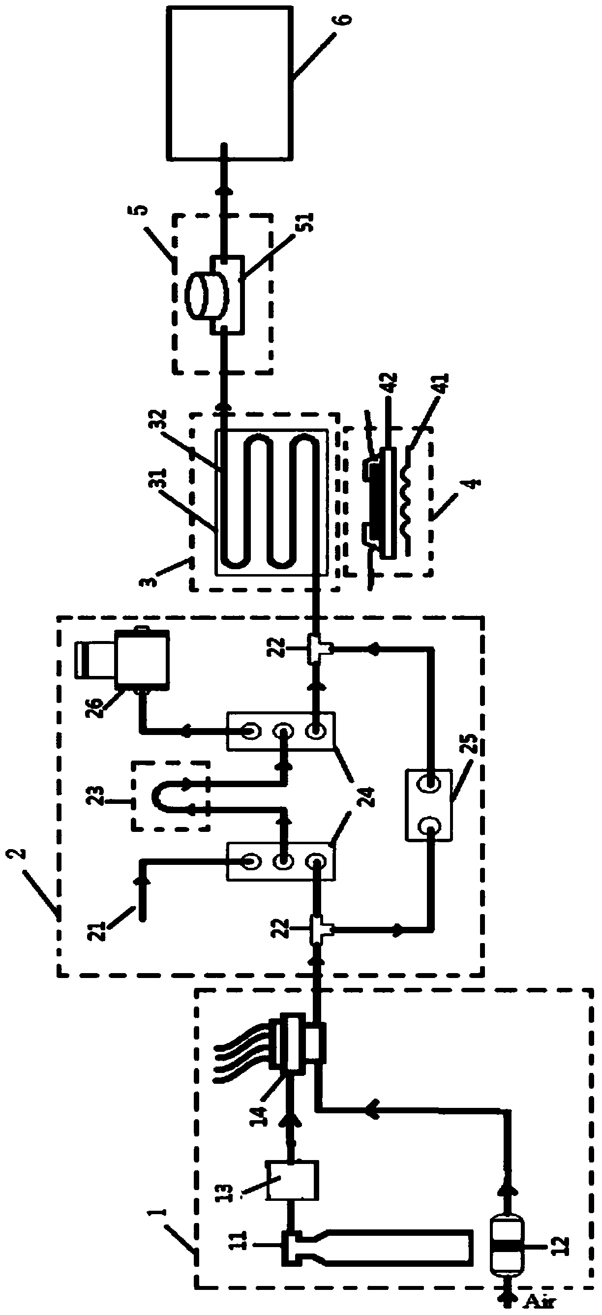

Image

  • Foul gas detection device based on micro-fluidic chip
  • Foul gas detection device based on micro-fluidic chip
  • Foul gas detection device based on micro-fluidic chip

Examples


Embodiment 1

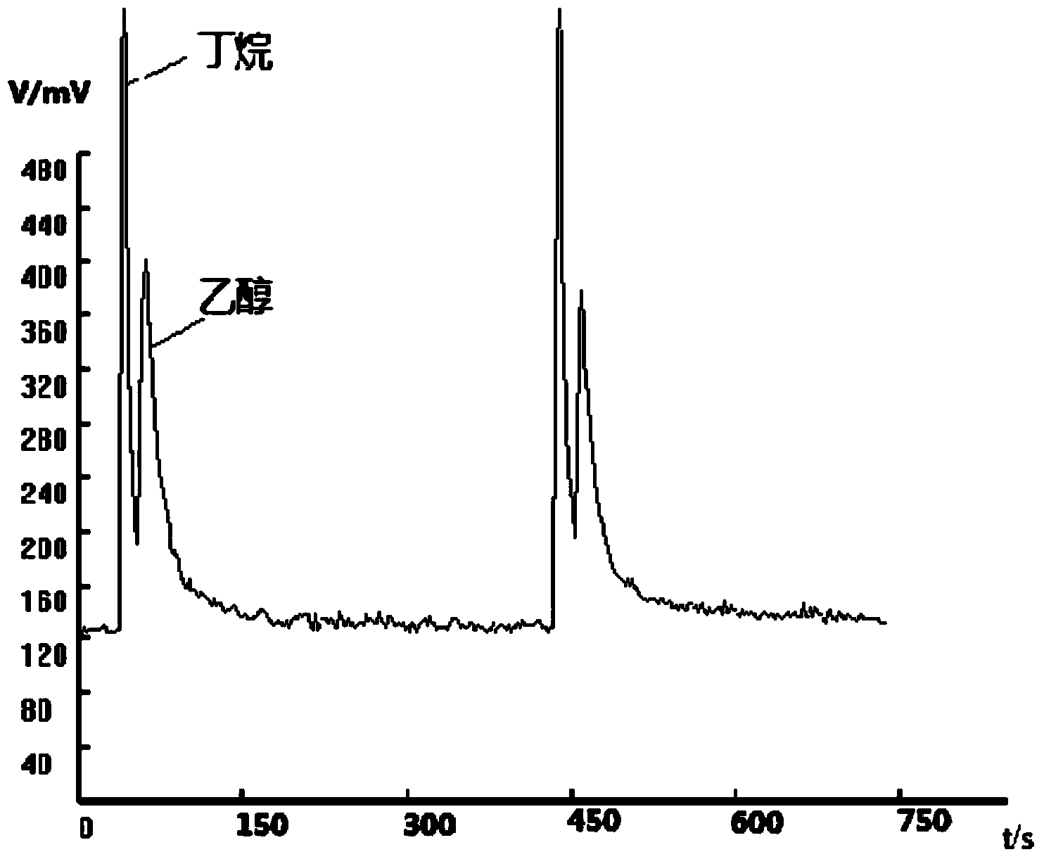
[0025] In this embodiment, the above-mentioned detection device is used, nitrogen is used as the carrier gas, the temperature is controlled at 50°C, the flow rate of the carrier gas is 20ml / min, and the photoionization detector adopts an ultraviolet lamp with an ionization energy of 10.6eV, which can quickly separate butane and ethanol The mixed gas can quickly determine the type of sample gas through database matching, and quantitatively analyze the content of each component of the sample gas. For the experimental results, see figure 2 . After 5 repeated sample injections, the experimental data are basically consistent, indicating that the detection device of the present invention has good reproducibility and high data reliability.

Embodiment 2

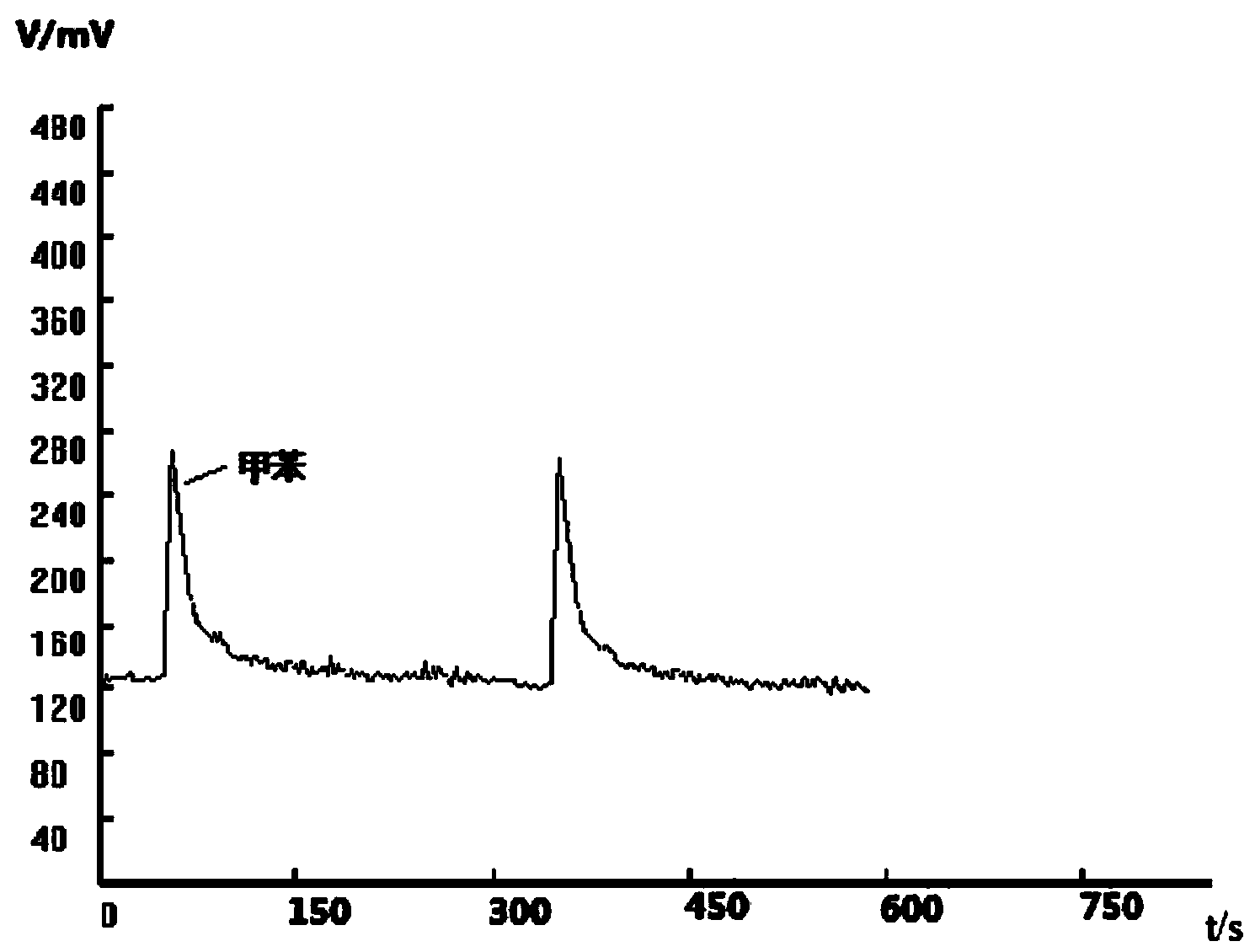
[0027] In this embodiment, the above detection device is used, air is used as the carrier gas, the temperature is controlled at 65°C, the flow rate of the carrier gas is 15ml / min, and the photoionization detector adopts an ultraviolet lamp with an ionization energy of 10.6eV, which can quickly detect toluene gas. The rapid matching of the database is used for qualitative and quantitative analysis of the sample gas. For the experimental results, see image 3 . After multiple sample injections, the experimental data remains basically consistent, indicating that the detection device of the present invention has good reproducibility and reliable detection data.

[0028] The detection device of the invention not only realizes quantitative analysis of gas components, but also further simplifies the structure of the detection device and improves its sensitivity without destroying the gas. The present invention uses microfluidic chip technology to concentrate the separation system on...


PUM


Abstract

The invention relates to a foul gas detection device based on a micro-fluidic chip. The foul gas detection device comprises a gas path system, a control system, a gas detection system and a data processing system, wherein the control system adopts a temperature control system; the gas detection system adopts a light ionization detector; the foul gas detection device is characterized by further comprising a sample injection system and a gas separation system; the sample injection system is connected with one side of the gas path system and one side of a gas separation system respectively through a left connection piece and a right connection piece; the control system is arranged on the lower part of the gas separation system; the other side of the gas separation system is connected with the gas detection system and the data processing system in sequence; the gas separation system adopts the micro-fluidic chip, wherein a fixed phase coats inside of a micro channel of the micro-fluidic chip; the sample injection system comprises a sample gas inlet, a connection piece, a quantification pipe, a three-way valve, a two-way valve and a diagram pump. The foul gas detection device can accurately and effectively control pressure of a gas path, and is stable in flow and high in detection precision; full separation of multi-component gas can be realized, so that qualitative and quantitative analysis on the multi-component gas is realized.

Description

technical field [0001] The invention relates to a malodorous gas detection system, in particular to a malodorous gas detection device based on a microfluidic chip. Background technique [0002] Odor pollution is a special kind of pollution in air pollution, which stimulates the olfactory organs of the human body and affects people's psychology. Malodorous gas is a general term for all odorous gases. The national standard for malodorous gases is defined as (GB14554-93): all gaseous substances that stimulate the olfactory organs and cause people's unpleasantness and damage the living environment. High-concentration odor pollution can even threaten human life and health. Therefore, strengthening the detection of odorous gases in the atmosphere is related to people's health, and it is also an effective measure to monitor environmental pollution. [0003] As we all know, the gas phase method is widely used, and its separation principle is to use the difference in the distributio...

Claims


Application Information

Patent Timeline
IPC IPC(8): G01N30/88
Inventor 张思祥张旭周围杨新颖侯晓玮李海古立锁张文强高涵
Owner HEBEI UNIV OF TECH
Learn More