High-efficiency dissolved air flotation system

A dissolved air flotation and high-efficiency technology, applied in the field of air flotation systems, can solve problems such as complex operation and management, unstable bubble effect, and limited number of bubbles, and achieve the effects of reduced operating costs, convenient remote monitoring, and high bubble density

Inactive Publication Date: 2014-07-23
辽宁华霆环保科技有限公司
View PDF3 Cites 15 Cited by
  • Summary
  • Abstract
  • Description
  • Claims
  • Application Information

AI Technical Summary

Problems solved by technology

This method is mainly used for small and medium-scale industrial wastewater treatment. Its disadvantages are: large power consumption, high investment cost; complex operation and management, inconvenient operation; easy fouling of electrodes and short service life, so it is rarely used in industry. use
Its disadvantages are: under normal pressure, the solubility of air is low, and the number of air bubbles is limited; airtight equipment is required to maintain vacuum, and operation and maintenance are difficult
The disadvantage is that the aeration head of the aerator is often blocked, it is difficult to debug, the effect of bubble generation is unstable, and there are few cases of successful operation in China

Method used


Image

  • High-efficiency dissolved air flotation system
  • High-efficiency dissolved air flotation system
  • High-efficiency dissolved air flotation system

Examples


Embodiment Construction

[0029] The specific embodiment of the present invention will be further described below in conjunction with accompanying drawing:

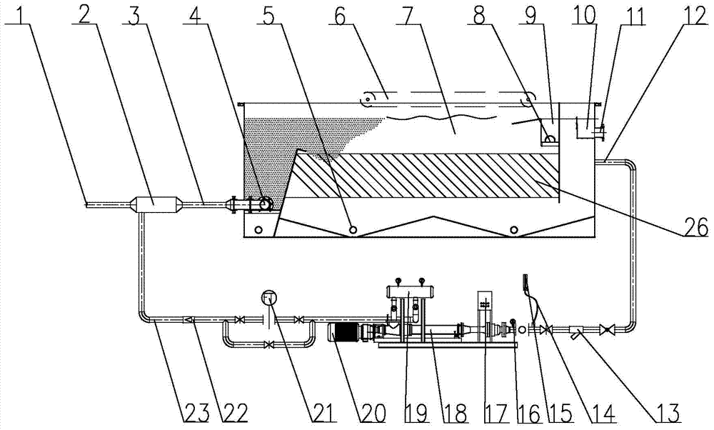
[0030] See figure 1 , is a structural schematic diagram of the present invention, a high-efficiency dissolved air flotation system of the present invention, including an air flotation tank 7, a slag scraper 6 installed in the air flotation tank 7, a slag discharge device and a water outlet device, and the air flotation tank drawn from the end of the air flotation tank 7 The gas-liquid mixing pump inlet pipe 12 is provided with an inlet pipe 14, and is connected to the gas-liquid mixing pump 20, the microbubble generator 19 through the gas-liquid mixing pipe 18, and the high-pressure saturated gas-dissolved water pipe 23 drawn from the microbubble generator 19 The dissolved air releaser 4 at the end of the water inlet pipe 3 of the air flotation tank is connected with the external sewage inlet pipe 1 through the T-shaped mixer 2 .

[0031] The air...


PUM

PropertyMeasurementUnit
particle diameteraaaaaaaaaa

Abstract

The invention relates to a high-efficiency dissolved air flotation system which comprises an air flotation tank, a slag scraper, a slag discharge device, a water outlet device and an air-liquid mixing pump water inlet pipe, wherein the slag scraper, the slag discharge device and the water outlet device are arranged in the air flotation tank; the air-liquid mixing pump water inlet pipe is led out from the tail end of the air flotation tank, the air-liquid mixing pump water inlet pipe is provided with an air inlet pipe and connected with an air-liquid mixing pump and a microbubble generator through an air-liquid mixing pipe; a high-pressure saturated dissolved air water pipe led out from the microbubble generator and an external sewage inlet pipe are communicated with a dissolved air releaser positioned on the tail end of the water inlet pipe of the air floatation tank through a T-shaped mixer. Compared with the prior art, the high-efficiency dissolved air flotation system has the beneficial effects that dissolved air generated through the system is good in water stability and high in bubble density, microbubbles with grain diameters of about 5 micrometers and generated through the system are more easily adhered to suspended substances and oil droplets which are contained in sewage and a better removing effect can be achieved because the dissolved air ratio of dissolved air water inside the system can achieve 30%-35% and is simple in structure, easy to debug, stable in operation, stable and reliable in operation, conserved in energy, reduced in consumption and high in automation degree.

Description

technical field [0001] The invention relates to an air flotation system in a water treatment process, which is mainly used for the purification treatment of waste water in rolling mills, steelmaking plants, coking plants, oil refineries and oil production plants, paper mills, food and chemical plants, and especially relates to a dissolved air flotation system system. Background technique [0002] At present, in the air flotation process of industrial wastewater and urban sewage treatment, according to the different methods of generating bubbles, air flotation can be divided into electrolytic flotation method, impeller air flotation method and dissolved air flotation method. [0003] The electrolytic flotation method uses an insoluble anode and cathode to pass through a 5-10V direct current to directly electrolyze the wastewater. The anode and the cathode generate hydrogen and oxygen respectively, forming a large number of tiny bubbles, adhering the suspended particles in th...

Claims


Application Information

Patent Timeline
Patent Type & Authority Applications(China)
IPC IPC(8): C02F1/24
Inventor 刘海瑞
Owner 辽宁华霆环保科技有限公司
Why Eureka
Try Eureka