
Water treatment method and equipment of photocatalytic composite membrane bioreactor

A technology of bioreactor and water treatment equipment, applied in the field of water treatment of photocatalysis-composite membrane bioreactor, to achieve the effect of strong sewage treatment capacity, less residual sludge and small footprint

Active Publication Date: 2014-06-18
TONGJI UNIV
View PDF9 Cites 17 Cited by
  • Summary
  • Abstract
  • Description
  • Claims
  • Application Information

AI Technical Summary

Problems solved by technology

[0007] In order to solve the deficiencies of the prior art, the purpose of the present invention is to solve the problem of removing trace pollutants in the water environment, and to provide a water treatment method and equipment for a photocatalytic membrane bioreactor

Method used


Image

  • Water treatment method and equipment of photocatalytic composite membrane bioreactor
  • Water treatment method and equipment of photocatalytic composite membrane bioreactor

Examples


Embodiment 1

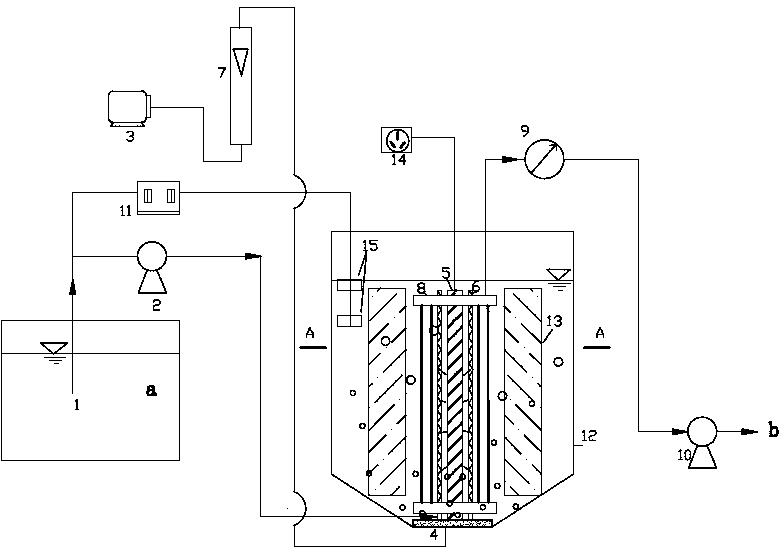
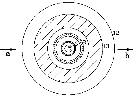
[0025] Embodiment 1: as figure 1 and figure 2 as shown,This device is mainly composed of aeration tank 12 and other auxiliary devices, including: water inlet tank 1, water inlet pump 2, air compressor 3, aeration disc 4, ultraviolet lamp 5, catalyst layer 6, gas flow meter 7, membrane module 8 , Vacuum pressure gauge 9, outlet pump 10, liquid level automatic control system 11, aeration tank 12, biofilm carrier 13, power supply 14 and float switch 15. Sewage containing trace pollutants enters between the ultraviolet lamp tube 5 and the catalyst carrier 6 from the bottom through the water inlet pool 1 . The bottom of the aeration tank 12 is provided with a microporous aeration disc 4 for aeration, and the dissolved oxygen concentration is kept at 4-6 mg / L. The center of the aeration tank 12 is vertically arranged with an ultraviolet lamp 5 surrounded by a titanium dioxide catalyst 6. The outer layer of the catalyst layer 6 surrounds the membrane module 8, and a biofilm ca...

Embodiment 2

[0027] Embodiment 2: Adopt the device described in embodiment 1, apply this device to the sewage containing tetracycline hydrochloride and carry out small-scale research. The operating parameters of the process are: the hydraulic retention time is 24h, the sludge age is 25 days, the sludge concentration is about 4000 mg / L, the influent flow rate is 0.25L / h, and the influent NH 4 + -N is about 90mg / L. The concentration of tetracycline hydrochloride is 400mg / L, and the light intensity is 360μW / cm 2 . When the light time was 120min, the removal rate of tetracycline hydrochloride reached 80%. 4 + -N removal rate reaches 95%, NH 4 + The average effluent concentrations of -N and tetracycline hydrochloride were 4.5 mg / L and 80 mg / L, respectively. After 24 hours of reaction time, the removal rate of tetracycline hydrochloride was 99.5%, and NH 4 + -N removal rate is 99%, NH 4 + -N and tetracycline hydrochloride average effluent concentrations are: 0.1mg / L and 2mg / L respecti...


PUM


Abstract

The invention belongs to the technical field of drinking water and sewage treatment, and specifically relates to a water treatment method and equipment of a photocatalytic composite membrane bioreactor for removing micro pollutants out of water. The process mainly consists of an aeration tank and other auxiliary devices. Sewage containing micro pollutants enters the aeration tank. An ultraviolet lamp tube loaded with a titanium dioxide catalyst is vertically distributed at the center in the tank, and the outer layer of the lamp tube is encircled by a membrane assembly and a biological membrane carrier mainly loaded with nitrifying bacteria in sequence. One part of micro pollutants in the sewage are removed by virtue of ultraviolet photo-catalysis, the biological membrane and ammonia nitrogen-containing wastewater generate nitration reaction to remove ammoniacal nitrogen, and in the nitration process, the biological membrane generates co-metabolism with the micro pollutants to further remove the pollutants. The process can have stable and efficient removing effect on various micro pollutants under a low-concentration organic carbon source condition.

Description

technical field [0001] The invention belongs to the technical field of drinking water and sewage treatment, and in particular relates to a water treatment method and equipment of a photocatalysis-composite membrane bioreactor for removing trace pollutants in water. Background technique [0002] Trace pollutants are a class of substances that have extremely low concentrations in the environment and can cause adverse effects on living organisms. In recent years, with the continuous development of environmental analysis technology, more and more new trace pollutants such as endocrine disrupting chemicals (trace pollutants), pharmaceuticals and personal care products (PPCPs), etc. detected in the environment. These trace pollutants will affect the chemical safety of reclaimed water, thereby bringing potential reuse risks. Therefore, the removal of trace pollutants is gradually becoming one of the key issues in the field of wastewater reuse. On the other hand, since these trace...

Claims


Application Information

Patent Timeline
Patent Type & Authority Applications(China)
IPC IPC(8): C02F9/14
Inventor 王荣昌王紫嫣袁红丹
Owner TONGJI UNIV
Learn More